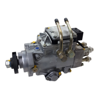
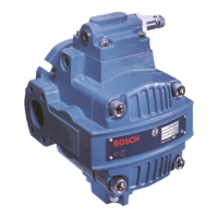
VPV Vane Pump 3
Specifications
General VPV 16 VPV 25 VPV 32
Displacement (Nominal) 1 in
3
/rev (16 cm
3
/rev) 1.5 in
3
/rev (25 cm
3
rev) 2 in
3
/rev (32 cm
3
/rev)
Displacement (Actual) 1.06 in
3
/rev (16.8 cm
3
/rev) 1.66 in
3
/rev (27.4 cm
3
rev) 2.04 in
3
/rev (32 cm
3
/rev)
Flow at 1750 RPM
1
7.57 GPM (28.6 L/min) 11.36 GPM (43.0 L/min) 15.15 GPM (57.3 L/min)
Maximum continuous pressure 3000 psi (210 bar)
Pressure compensating Single stage 200-3000 psi (14-210 bar) Minimum pressure of 190 PSI
range Two stage 300-3000 psi (20-210 bar) Minimum pressure of 290 PSI
Maximum transient spike pressure 3800 psi (260 bar) 4000 psi (280 bar)
Maximum case pressure 10 psi (0.7 bar)
Speed range 1150-1800 RPM
Direction of rotation (viewed from shaft end) Right hand (clockwise)
Case drain flow 1000 psi (70 bar) 0.6 GPM (2.3 L/min) 0.6 GPM (2.3 L/min)
while compensating 2000 psi (140 bar) 0.9 GPM (3.4 L/min) 1.1 GPM (4.2 L/min)
@ 1800 RPM 3000 psi (210 bar) 1.26 GPM (4.8 L/min 1.4 GPM (5.3 L/min)
Maximum inlet vacuum at sea level 6 in. HG (152 mm HG)
Mounting
2
- SAE 2-bolt flange (ISO 3019/1) S.A.E. ‘A’ S.A.E. ‘B’
2-bolt flange 2-bolt flange
Mounting Position Unrestricted
Inlet #16 S.A.E. #24 S.A.E
Outlet #12 S.A.E. #16 S.A.E.
Port sizes Case drain #8 S.A.E.
Clipper control drain (optional) #6 S.A.E.
Remote control (optional) #4 S.A.E.
Drive Pump to be connected to prime mover by means of a flexible coupling that is aligned
to a maximum of .006” (.152mm) total indicator reading. No overhung or side loads
permitted. Alignments greater than .006” indicator reading could cause increased
noise and vibration as well as premature shaft seal wear resulting in leakage.
Fluid recommendations A premium quality hydraulic oil with anti-wear additives is recommended, but not
required. Refer to publication S-106 “Petroleum Hydraulic Fluids” for a list of fluids
which meet or exceed the necessary lubrication requirements. Consult factory for
use with water base fire resistant fluids.
Minimum 100 SUS (21 cSt)
Fluid viscosity at Maximum 1000 SUS (216 cSt)
operating temperature Optimum 150-250 SUS (32-54 cSt)
Maximum start-up 4000 SUS (864 cSt)
Fluid temperature Normal inlet fluid temperature should not exceed 140°F (60° C). Always select a fluid
for optimum viscosity at operating temperature. Consult factory for applications assis-
tance when inlet fluid temperatures over 140° F (60° C) are expected.
Seals Fluorocarbon Standard
Filtration Fluid cleanliness per ISO/DIS 4406 should be 18/15 or better for pressures of 2000 psi or
less. For continuous operating pressures of 2000 to 3000 psi, fluid cleanliness should be
17/13 or better.
Response time Full flow to 20-35 ms 20-35 ms
(circuit dependent) minimum flow
Recovery time Minimum flow 50-135 ms – 70-185 ms –
(circuit dependent) to full flow single stage compensator single stage compensator
Weight Single stage 34 lbs. (16.5 kg) 61 lbs. (28 kg)
Two stage 38 lbs. (17.3 kg) 65 lbs. (28.5 kg)
1
Flows are actual. Volumetric efficiencies shown in technical data taken into account.
2
Metric
4-bolt flange
available
(ISO 3019/2)
available. Please consult factory.