'
E
L
SYSTEM FILL
Heating return
Hose
WATER
SYSTEMS
& PIPEWORK
----~
'
--------------F
...
------D
Heating
return
Cylinder return
S PLAN LAYOUT
Y PLAN LAYOUT
SEALED SYSTEM LAYOUT
Heating flow
SYSTEM
MAKE
UP
Heating return
Auto
Mains
supply
Stop
cock
Make up
vessel
WATER SYSTEMS &
PI
PEWORK
PLASTIC PIPEWORK:
•
Any plastic pipework must
have
a polymeric
barrier with
600
mm
(minimum) length of
copper or
steel pipe connected to the boiler.
Plastic
pipework used for underfloor heating
must be
correctly controlled with a thermo-
static blending valve limiting the temperature
of the circuits to approx.
50°C.
The
pipework from the boiler to the blending
valve
must be
in
copper or steel (protected
from corrosion).
CONNECTIONSNALVES:
• All
system connections, taps and mixing
valves must be capable of sustaining a pres-
sure up to 3
bar.
Radiator valves should conform to
BS2767:10.
Do not use galvanised pipes or radiators.
• All other valves should conform to BS1010.
On
new installations, or extensions to exist-
ing systems where a radiator previously did
not exist, each radiator
should be fitted with
a
TRV,
except the one fitted
in
the same
room/area
as
the room thermostat.
On boiler only replacement jobs, it is recom-
mended, (but not mandatory,) to fit a TRV
on
each radiator. It
is,
however, a requirement,
for energy conservation purposes, to
recom-
mend to the customer that a
TRV
is fitted to
each radiator.
• An automatic bypass
may
be required,
(downstream
of
the pump),
in
order to main-
tain the minimum flow-rate through the appli-
ance.
• A drain
cock
should
be
fitted
at
the
low-
est
point
of
the
heating
circuit
and
beneath
the
appliance.
•
An air vent is required at the highest point
on
the system.
SandY
PLAN SYSTEM:
A Static Head - Minimum static head 250mm
measured from the highest point
in
the heat-
ing system (top surface of the appliance or
highest point
in
the heating system) to the
water
level
in
the feed and expansion tank.
B Heating
Vent (22mm minimum)
C Primary Cold Feed
(15mm
minimum)
D Diverter
Valve
E Pump
F Automatic Bypass
G Radiator
Valve (Flow)
H Lockshield
Valve
(Return)
FULLY
PUMPED SEALED SYSTEM:
The
sealed system must be filled using a
WRAS
approved filling loop or comply with
the diagram opposite for
System fill
Do not use galvanised pipes or radiators.
Expansion
Vessel
Pressure
Gauge
K
Relief
Valve
L Stop
Valve
Fixed Cylinder Type or sealed
systems approved connection
INSTALLATION & SERVICING INSTRUCTIONS
FOR
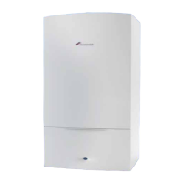
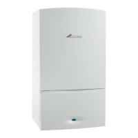
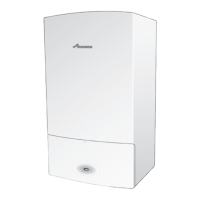
WORCESTER BOSCH GREENSTAR 30CDI/40CDI Coc,ectlocal
~ORCESTER
6 720
614
556a
(2007/07)
Bosch
Group

 Loading...


