Fault finding and diagrams
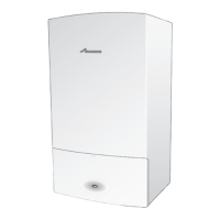
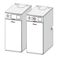
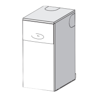
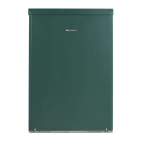
Greenstar Utility
ErP -
6 720 821 751 (2018/04)42
8.2 Burner fault indicator diagnostics
When the lockout LED illuminates, the burner will attempt to restart only after pressing the reset button. After that, if the burner is working properly, the
trip can be attributed to a temporary fault that is not dangerous.
Otherwise, if the trip persists, the cause of the fault must be sought and the solutions indicated in Table must be implemented.
Key to symbols
8.3 Riello control box
8.3.1 Control box LED codes
Problem Possible cause Fault indicator Possible solution/check
The burner does not start Lack of electrical supply, OFF ▶ Check presence of voltage on the L - N pin plug
when there is heat demand. ▶ Check the conditions of the fuses
▶ Check the safety thermostats are not in lockout
The flame detector sees
extraneous light.
▶ Eliminate the extraneous light
The connections in the control
box are wrongly inserted.
OFF ▶ Check and correct all the plugs and sockets properly
The pre-heater link is missing or
incorrectly fitted.
▶ Check and connect link correctly/replace link
The burner goes into lockout mode
before or during the pre-purging.
The flame detector or sees
extraneous light.
▶ Check for and eliminate any extraneous light
Burner runs normally in the The photocell is dirty. Red ▶Clean it
pre-purge and ignition cycle and The photocell is faulty. Steady ON ▶Replace it
looks out after about 5 seconds. Flame moves away or fails. ▶ Check pressure and output of the fuel
▶Check air output
▶ Check oil nozzle
▶ Check the coil of solenoid valve
Burner starts with an ignition delay The ignition electrodes are
damaged or incorrectly
positioned.
OFF ▶ Replace the blast tube and electrode assembly
Air output is too high. ▶ Set the air output according to the instructions of this
manual
Oil nozzle dirty or worn ▶Replace it
Table 18 Burner fault indicator diagnostics
ON OFF Colour code
Red
Green
Table 19
Lockout types (burner in lockout)
Refer to Fault finding chart, section 8.3.2, go to line number on chart
RED steady ON
Lockout for no flame after safety time
[3]
RED 0.5 seconds ON/ RED 0.5 seconds OFF
Lock out for false flame signal
[5a]
RED 0.2 seconds ON /RED 0.2 seconds OFF
Lock out for maximum number of flame loss re-lights
[9]
Table 20
RED 2.5 seconds ON / ORANGE 0.5 seconds ON
Lock out for fan motor failure
[3d]
RED 2.5 seconds ON / GREEN 0.5 seconds ON
Lock out for oil valve circuit driver failure
[8c]
ORANGE 0.5 seconds ON / GREEN 0.5 seconds ON
Lock out for EEPROM failure
Replace
control
box
Red 0.5s ON / Red 2.5s OFF
Max pre-heat time exceeded (10 minutes)
[2]
Lockout types (burner in lockout)
Table 20

 Loading...


