Appliance information
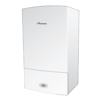
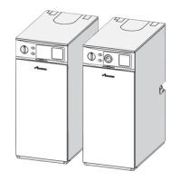
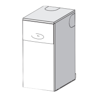
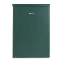
Greenstar Utility
ErP -
6 720 821 751 (2018/04)8
3.4 Layout & components
Fig. 2 Appliance components (The diagram excludes the top, front and RH side casing panels.)
1 CH flow connector (left and right) 2 Flue over heat thermostat 3 Air pressure switch 4Air sample point
5 Air supply duct to burner 6 Appliance overheat thermostat 7 Condensate pipe connector 8 Condensate drain pipe
9 Condensate trap 10 Oil supply isolation valve 11 Burner mounting flange 12 Primary HE drain point
13 Burner 14 Burner fault indicator/reset 15 Combustion chamber access door 16 Primary HE baffle
17 Flue overheat manual reset 18 Overheat manual reset 19 Control knob 20 Control panel
21 Flue manifold access cover 22 Flue gas sample point 23 Secondary HE baffles 24 CH return pipe
25 Secondary air vent
6720821751-0
4.3W
o
1
2
3
19
20
7
1
6
5
4
8
9
10
12
13
14
15
16
18
17
21
22
23
24
25
11

 Loading...


