50
Test Procedures
3. Transducer Phase Test
3.1 Apply a DC voltage of 10V, positive
applied to the positive tab of the dual
banana jack on the line array test cable and
negative applied to negative (gnd) tab.
3.2 All of the driver cones should move
outward when the DC voltage is applied.
Rewire any incorrectly connected transduc-
ers.
4. Line Array Sweep Test
4.1 Set up the upper or lower line array
section as shown in the figure on the previ-
ous page.
4.2 Apply a 100 Hz, 10 Vrms sine wave to
the input.
4.3 While listening to the output of the
system, sweep the input frequency slowly
from 100 Hz to 15 kHz. Listen carefully for
any extraneous noises such as buzzing and
ticking.
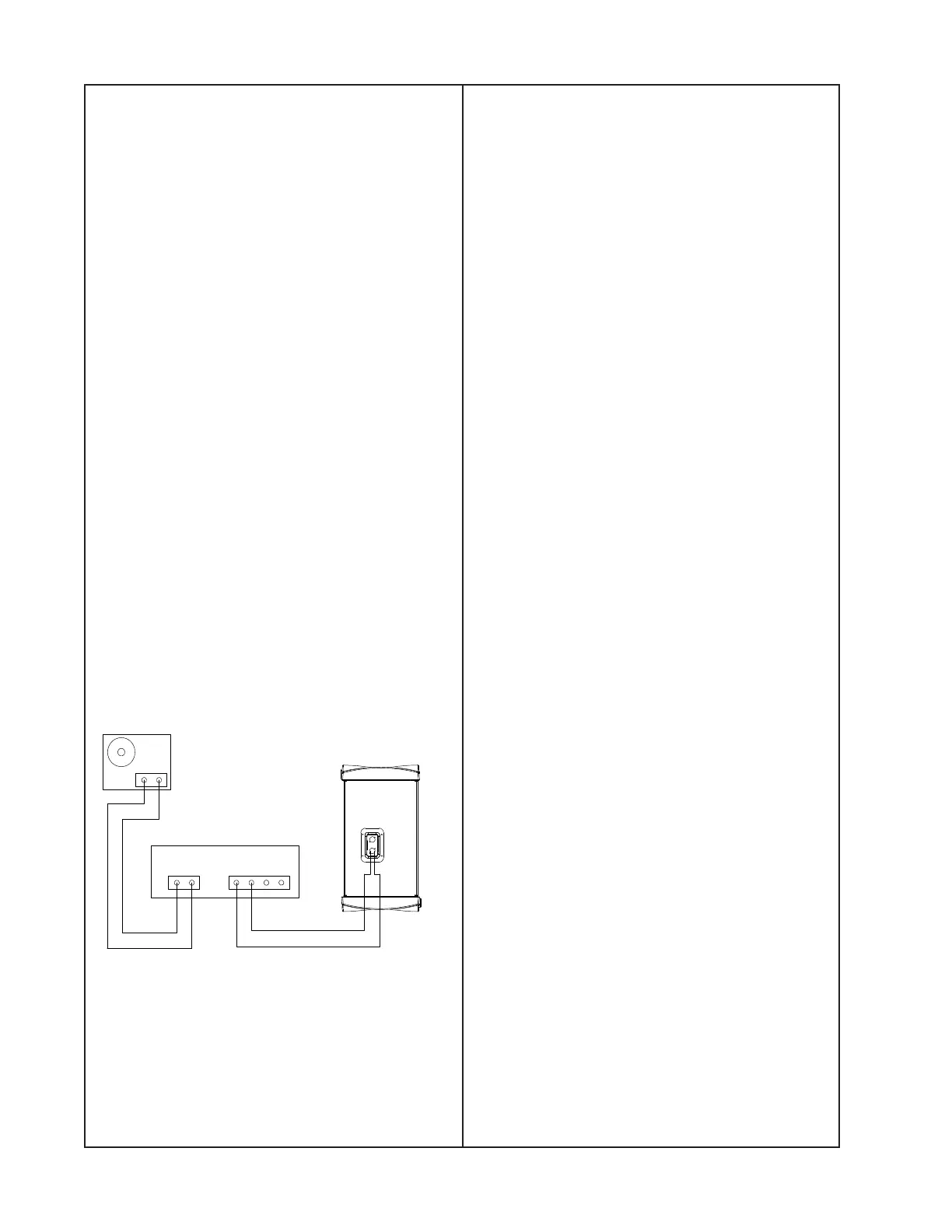
B1 Bass Module Tests
Set up the unit under test as shown below.
1. Air Leak Test
1.1 Apply a 100 Hz, 20 Vrms sine wave to
the unit under test.
1.2 Listen carefully for air leaks from around
the end cap, the transducers and the grille.
Test duration should be 5 seconds minimum.
2. Transducer Rub and Tick Test
2.1 Remove the transducer you wish to test
using the disassembly procedures in this
manual.
2.2 Connect a signal generator directly to the
terminals of the transducer assembly under
test.
2.3 Apply a 10 Hz, 10 Vrms signal to the
transducer assembly.
2.4 Listen carefully for any extraneous
noises such as rubbing, scraping or ticking.
Note: To distinguish between normal sus-
pension noise and rubs or ticks, displace the
cone slightly with your fingers. If the noise
stays the same, it is normal suspension
noise and the driver is good. Suspension
noise will not be heard with program mate-
rial.
3. Transducer Phase Test
3.1 Apply a DC voltage of 20V, positive
applied to the positive tab of the dual
banana jack on the bass module test cable
and negative applied to negative (gnd) tab.
3.2 Note that all driver cones move outward
when the DC voltage is applied.
3.3 Rewire any incorrectly connected trans-
ducers.
4. System Sweep Test
4.1 Set up the bass module as shown at left.
4.2 Apply a 10 Hz, 20 Vrms sine wave to the
Neutrik
®
Speakon
®
input connector.
4.3 While listening to the output of the
system, sweep the input frequency slowly
from 10 Hz to 400 Hz. Listen carefully for
any extraneous noises such as buzzing and
ticking.
Power Amplifier
INPUT OUTPUT
Audio Signal
Generator
B1 Bass Module
Test Cable
B1 Bass Module
 Loading...