49
Test Procedures
1.1 Connect the AC mains cord to the back
of the unit under test. Plug the other end of
the AC cord into the Hi-Pot tester.
Connect the Return lead to the Analog Input
jack using an adapter and cable.
1.2 With the tester set to the above param-
eters, perform the test. If the unit fails,
return the unit to the technician for trouble-
shooting and and repair of the problem.
Once the unit is repaired, repeat the Hi-Pot
test to ensure the unit is safe to return to the
customer.
2. Ground Bond Test
IMPORTANT: This test MUST be performed
if the ground connection from the AC inlet to
the chassis has been disturbed as part of a
repair. This test ensures that the ground
connection can take the full current of the AC
line if needed due to a product failure.
It does this by measuring the current han-
dling capability of the ground connection by
putting a high current through the ground
blade of the AC line cord and measuring the
leakage current on the exposed metal part
of the chassis.
2.1 Plug the AC line cord into the AC
adapter box supplied with the Hi-Pot tester.
Connect the return line from the Hi-Pot tester
to an exposed metal section of the chassis.
Ensure a good electrical connection.
2.2 Perform the ground bond test in
accordance with the parameters below.
- 10Amps, < 12VAC open circuit,
< 0.1 Ohms.
2.3 If the unit passes this test and the Hi-
Pot tests, it can be returned to the customer.
If the unit fails this test, it must be returned
to the repair tech for troubleshooting and
repair and then be retested.
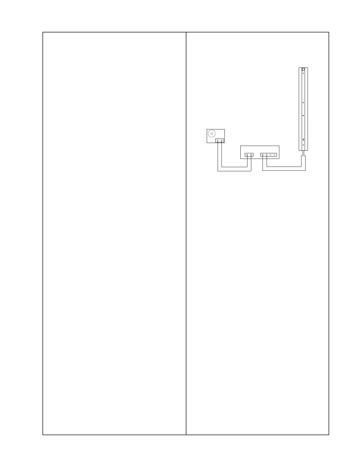
L1 Model II Line Array Tests
Set up the unit under test as shown below.
1. Air Leak Test
1.1 Apply a 100 Hz, 10 Vrms sine wave to
the unit under test.
1.2 Listen carefully for air leaks from around
the end cap, the transducers and the grille.
Air leaks will be heard as a hissing or sput-
tering sound. All repairs must be hidden.
Test duration should be 5 seconds minimum.
2. Transducer Rub and Tick Test
2.1 Remove the transducer you wish to test
using the disassembly procedures in this
manual.
2.2 Connect a signal generator directly to the
terminals of the transducer assembly under
test.
2.3 Apply a 20 Hz, 5 Vrms sine wave to the
transducer assembly.
2.4 Listen carefully for any extraneous
noises such as rubbing, scraping or ticking.
Note: To distinguish between normal sus-
pension noise and rubs or ticks, displace
the cone slightly with your fingers. If the
noise stays the same, it is normal suspen-
sion noise and the driver is good.
Power Amplifier
INPUT OUTPUT
Audio Signal
Generator
Upper or Lower
L1 Line Array
Upper or Lower L1
Line Array Test Cable
 Loading...