48
Test Procedures
5. Bass Line Output Test
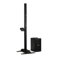
5.1 Set up the L1
®
Model II power stand with
an L1 Model II line array and B1 bass mod-
ule connected as shown on pages 6 - 8 of
this manual.
5.2 With a 500mVrms audio signal applied to
the power stand, listen to the output of the
line array.
5.3 Plug an un-balanced TRS cable into the
bass line output jack located on the power
stand input/output panel. Verify that the
output of the line array mutes briefly when
the TRS cable is plugged in. This muting
action indicates that the DSP in the power
stand has detected the connection of the
TRS cable.
6. L1 Model II System Sweep Test
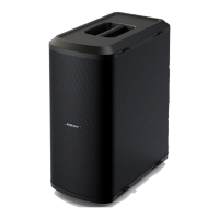
6.1 Set up the L1 Model II power stand with
an L1 Model II line array and two B1 bass
modules connected.
6.2 Set the power stand trim knob to mid-
point.
6.3 Using a balanced TRS cable, apply a
100mVrms, 20 Hz signal to the power stand
line input jack.
6.4 Sweep the input frequency from 20 Hz to
20 kHz. Verify that the system does not
produce any audible acoustical or mechani-
cal abnormalities.
7. ToneMatch
®
(M) Port Test
7.1 Set up the L1 Model II power stand with
an L1 Model II line array and B1 bass mod-
ule connected as shown on pages 7 & 8 of
this manual.
7.2 Connect a T1 ToneMatch Audio Engine
to the ToneMatch port located on the power
stand input/output panel as shown on page
9 of this manual..
7.3 Apply a 10mVrms, 20Hz signal to either
the channel 4 or 5 input on the T1. Verify
that the T1 powers up and appears to
operate properly. Note: Refer to the T1
ToneMatch owner’s guide on the Bose Live
Music Technology Group website at
http://www.bose.com/musicians if you have
any questions about operation of the T1.
7.4 Sweep the input frequency from 20 Hz
to 20 kHz. Verify that the audio output
sounds normal across the audio output
range.
Hi-Pot Test
THIS IS A MANDATORY TEST
CAUTION - All units that are disassembled
as part of a repair MUST be Hi-Pot tested
before being returned to the customer.
This test applies a high voltage to the AC
line cord and measures the current leakage
to the chassis and/or other metal parts on
the outside of the unit to check for potential
shock hazards.
- If the unit fails Hi-Pot test, it must be
rerturned to the technician for troubleshoot-
ing and repair of the problem, after which it
must be Hi-Pot tested again to ensure that it
now passes the test.
- This test requires a Hi-Pot tester and
associated cables to perform this test.
There is a PDF file located on the L1 Model
1S product specific page on the Bose Ser-
vice web site that details how to perform this
test.
Hi-Pot Tester Settings:
100-120V units: Voltage Setting =
2.12KVDC, High Current = 3.5ma, Low
Current = 0ma, Ramp Time = 1 Second,
Dwell Time = 1 Second, Continuity OFF
220-240V units: Voltage Setting =
3.54 KVDC, High Current = 3.5ma, Low
Current = 0ma, Ramp Time = 1 Second,
Dwell Time = 1 Second, Continuity = OFF
 Loading...