Page 20 User Guide English
User Guide pro.Bose.com
Setup and Configuration
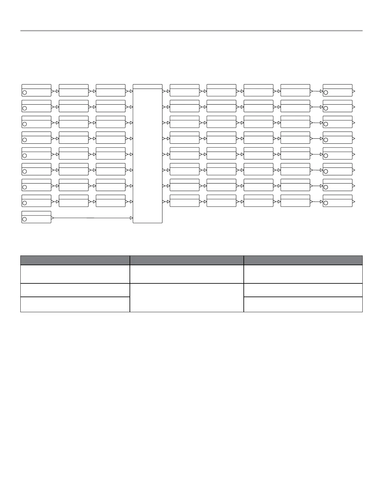
Figure 11 shows the basic signal flow and available DSP functions available to manipulate each individual input channel. Some
functions and advanced parameters can only be modified using ControlSpace
®
Designer™ software. See “Function Table” on page 40
to view configurations required to access functions and features.
Figure 11. Simplified DSP block diagram
Analog In
In A
Analog In
In B
Analog In
In C
Analog In
In D
Analog In
In E
Analog In
In F
Analog In
In G
Analog In
In H
Amp Output
Out 1
Amp Output
Out 2
Amp Output
Out 3
Amp Output
Out 4
Amp Output
Out 5
Amp Output
Out 6
Amp Output
Out 7
Amp Output
Out 8
Signal Generator
PEQ-5band
PEQ-5band
PEQ-5band
PEQ-5band
PEQ-5band
PEQ-5band
PEQ-5band
PEQ-5band
Array EQ
Matrix
A
1
Array EQ
Array EQ
Array EQ
Array EQ
Array EQ
Array EQ
Array EQ
Band Pass
Band Pass
Band Pass
Band Pass
Band Pass
Band Pass
Band Pass
Band Pass
SpeakerPEQ
SpeakerPEQ
SpeakerPEQ
SpeakerPEQ
SpeakerPEQ
SpeakerPEQ
SpeakerPEQ
SpeakerPEQ
Delay
Delay
Delay
Delay
Delay
Delay
Delay
Delay
Limiter
Limiter
Limiter
Limiter
Limiter
Limiter
Limiter
Limiter
B
2
C
3
D
4
E
5
F
6
G
7
H
8
Signal Generator
Configuration Methods
There are three methods to configure the PM8500 amplifier for use. The table below shows those methods and describes functionality
differences between the methods.
Method of Configuration Advantage Disadvantage
Local front panel Fast, easy access to basic loudspeaker processing and
control options.
Lacking graphical tools, control and DSP functions only avail-
able using ControlSpace Designer software such as input and
speaker equalization.
USB connection to ControlSpace Designer software Full-featured control and visibility over all DSP functions.
Graphical tools available to help create EQs for 3rd party
loudspeakers, realtime display and monitoring. With RJ45
connection, multiple amplifiers can be configured and
monitored from a PC.
Requires a PC running the ControlSpace Designer software
and a USB connection.
RJ45 connection to ControlSpace Designer software
(PM8500N only)
Requires the PM8500N amplifier, a PC running the
ControlSpace Designer software, and a network connection.

 Loading...