Assembly Guide
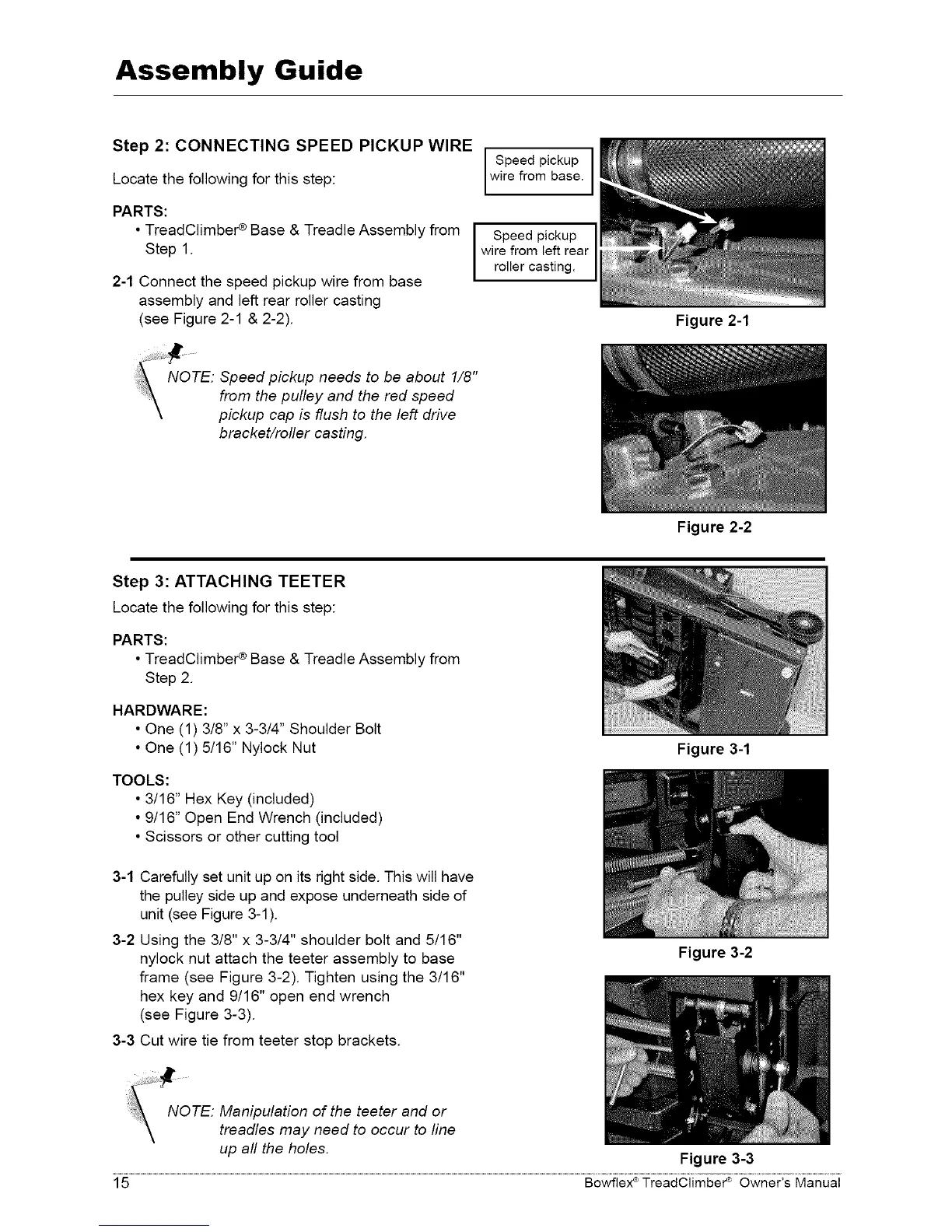
Step 2: CONNECTING SPEED PICKUP WIRE
Locate the following for this step:
PARTS:
• TreadClimber ¢ Base & Treadle Assembly from
Step 1.
2-1 Connect the speed pickup wire from base
assembly and left rear roller casting
(see Figure 2-1 & 2-2).
NOTE: Speed pickup needs to be about 1/8"
from the pulley and the red speed
pickup cap is flush to the left drive
bracket/roller casting.
Speed pickup I
wire from base.
I Speed pickup
wire from left rear
roller casting.
Step 3: ATTACHING TEETER
Locate the following for this step:
PARTS:
• TreadClimber ¢ Base & Treadle Assembly from
Step 2.
HARDWARE:
• One (1) 3/8" x 3-3/4" Shoulder Bolt
• One (1) 5/16" Nylock Nut
TOOLS:
• 3/16" Hex Key (included)
• 9/16" Open End Wrench (included)
• Scissors or other cutting tool
3-1 Carefully set unit up on its right side. This will have
the pulley side up and expose underneath side of
unit (see Figure 3-1).
3-2 Using the 3/8" x 3-3/4" shoulder bolt and 5/16"
nylock nut attach the teeter assembly to base
frame (see Figure 3-2). Tighten using the 3/16"
hex key and 9/16" open end wrench
(see Figure 3-3).
3-3 Cut wire tie from teeter stop brackets.
NOTE: Manipulation of the teeter and or
\
treadles may need to occur to line
up all the holes.
Figure 2-1
Figure 2-2
Figure 3-1
Figure 3-2
Figure 3-3
15 Bowflex ®TreadClimber _ Owner's Manual