Assembly Guide
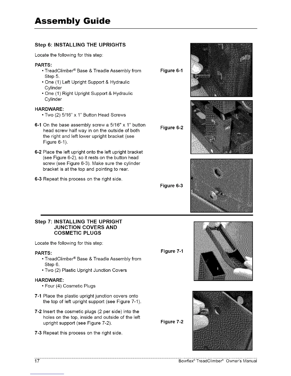
Step 6: INSTALLING THE UPRIGHTS
Locate the following for this step:
PARTS:
• TreadClimber ¢ Base & Treadle Assembly from
Step 5
• One (1) Left Upright Support & Hydraulic
Cylinder
• One (1) Right Upright Support & Hydraulic
Cylinder
HARDWARE:
• Two (2) 5/16" x 1" Button Head Screws
6-1 On the base assembly screw a 5/16" x 1" button
head screw half way in on the outside of both
the right and left lower upright bracket (see
Figure 6-1 )
6-2 Place the left upright onto the left upright bracket
(see Figure 6-2), so it rests on the button head
screw (see Figure 6-3) Make sure the cylinder
bracket is at the top and pointing to rear
6-3 Repeat this process on the right side
Figure 6-1
Figure 6-2
Figure 6-3
Step 7: INSTALLING THE UPRIGHT
JUNCTION COVERS AND
COSMETIC PLUGS
Locate the following for this step:
PARTS:
• TreadClimber ¢ Base & Treadle Assembly from
Step 6
• Two (2) Plastic Upright Junction Covers
HARDWARE:
• Four (4) Cosmetic Plugs
7-1 Place the plastic upright junction covers onto
the top of left upright support (see Figure 7-1 )
7-2 Insert the cosmetic plugs (2 per side) into the
holes on the top, inside and outside of the left
upright support (see Figure 7-2)
7-3 Repeat this process on the right side
Figure 7-1
Figure 7-2
17 Bowflex ®TreadClimber _ Owner's Manual