23
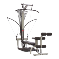
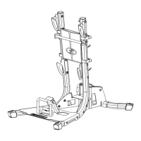
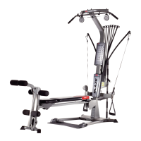
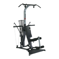
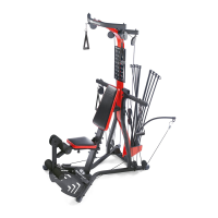
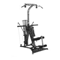
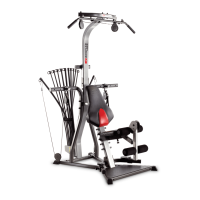
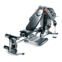
Assembling Your Bowflex Ultimate
®
2
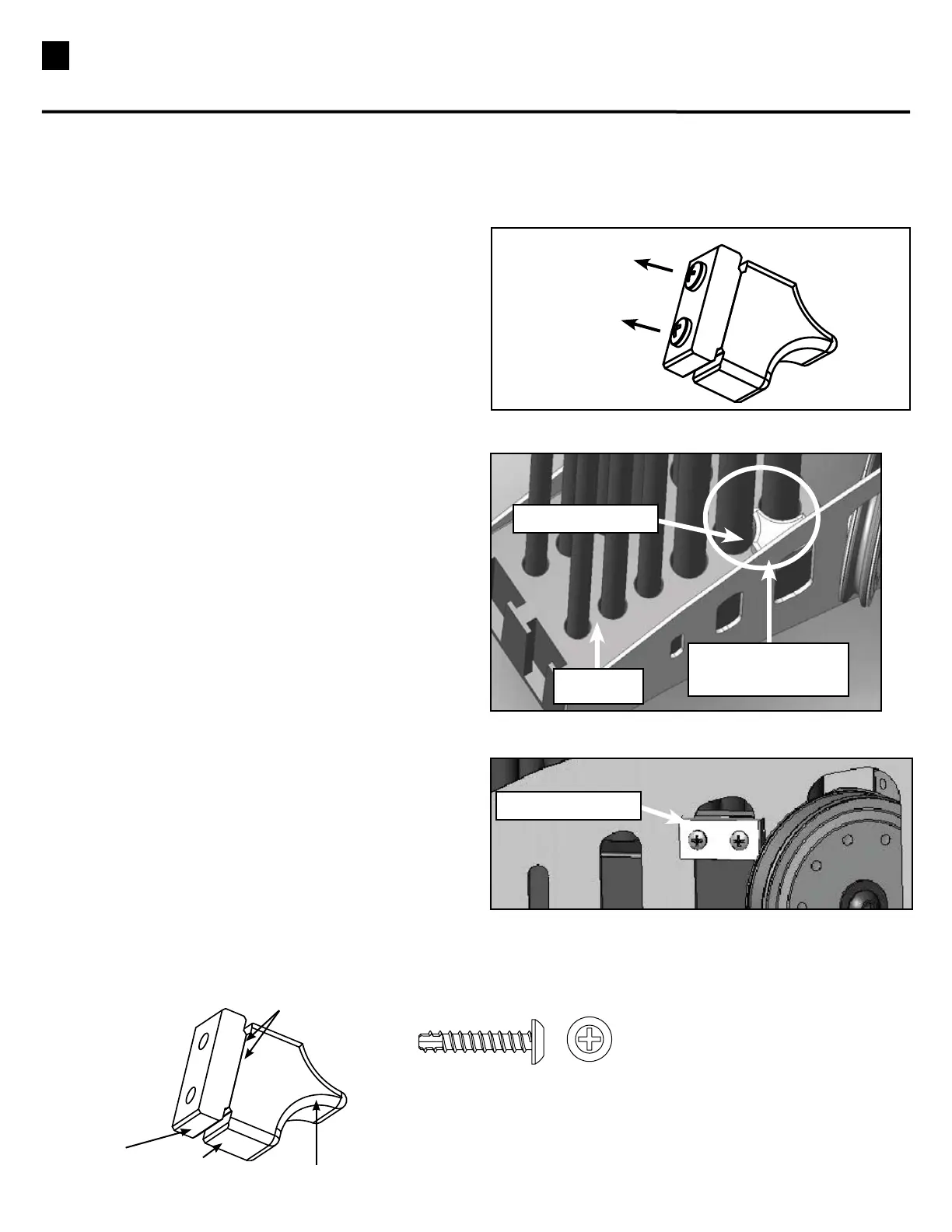
Unscrew
Figure B
Figure C
Insert into slot of
Rod Box Frame
Rod Box
Backing Plate
Qty:2
SelfThreadingScrews(#10x1”)
Rod Box Retainer (screws are pre-installed)
Notched Lip
Curved Side
Backing
Plate
Face
Place
STEP 7B
Parts:
•1RodBoxRetainer
Tool :
•PhillipsHeadScrewDriver
Note: RodBoxscrewsmustbeinstalledbefore
proceeding.
7B-1 Remove both screws connecting the backing
plateandthefaceplate(SeeFigureA).
7B-2StandfacingtherearoftheBowflexUltimate
®
2
unit.Placethebackingplate(largerpiece),withthe
curvedsidefacingup,inbetweenthetworight-side
50lb.rods(SeeFigureB).Verifythatthenotchedlip
ofthebackingplateislocatedintheslotoftheBox
Frame.
7B-3Matchupthefaceplate(thinnerpiece)tothebacking
plateontheoutsideoftherodbox.Makesurethat
thenotchedlipofbothbackingplatesaretouching
andthattheholesarealigned.
7B-4Fastenbothscrewsintothelinedupholes(See
FigureC).Tightenuntilsnugandthenanother
quarterturn.
Figure A
Face Plate
After installing the Rod Box in Step 7, install the Rod Retainer.