18
For example, if the input signal is 300 Hz, the stable data can be obtained using the 200 Hz filter.
Step 5: Speed selection.
Each filter has a different test speed, choosing the right measurement speed based on the filter will
result in more accurate test results and/or faster test speeds.
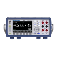
3.3.4 DC Current
Step 1: Using either the 3 A or 10 A input terminal, configure the test leads as follows:
Use the 10 A terminal for current measurements greater than 3 A.
Step 2: Press on the front panel then press to select the DCI function and enter the DCI
function interface.
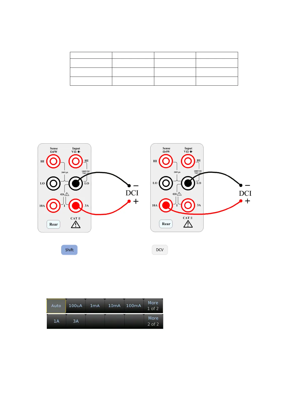
Step 3: Range adjustment.
Select the input terminal for the test signal. If you select 10 A input terminal, there is only 10 A range.
If you select 3 A input terminal: 100 uA, 1 mA, 10 mA, 100 mA, 1 A, 3 A, or Auto ranges are available.
Select the range using the softkeys:
Step 4: Set the integration time.
The setting of the integration time affects the measurement speed and measurement accuracy. The
longer the integration time, the higher the accuracy but the slower the measurement.