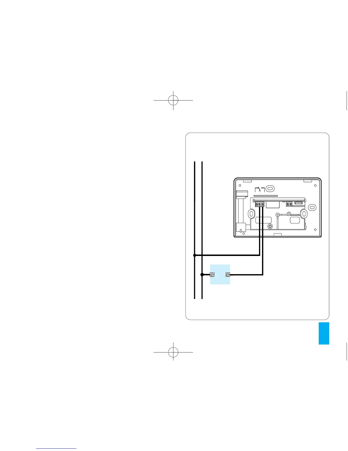
Fig. 8
LOAD
ATTENTION. For the unit to work properly, we rec-
ommend that it should be mounted on a flat surface.
Be careful not to tighten the screws excessively.
ELECTRICAL CONNECTIONS
The wiring will depend on the type of equipment to
be controlled by the thermostat: refer to the dia-
gram in fig. 8 or 9. Refit the terminal block cover.
KEY
Mains power supply wires
L=live
N = neutral
Relay contacts
NC = normally closed contact
C = common
NA = normally open contact
Remote control inputs
1 input
2 input