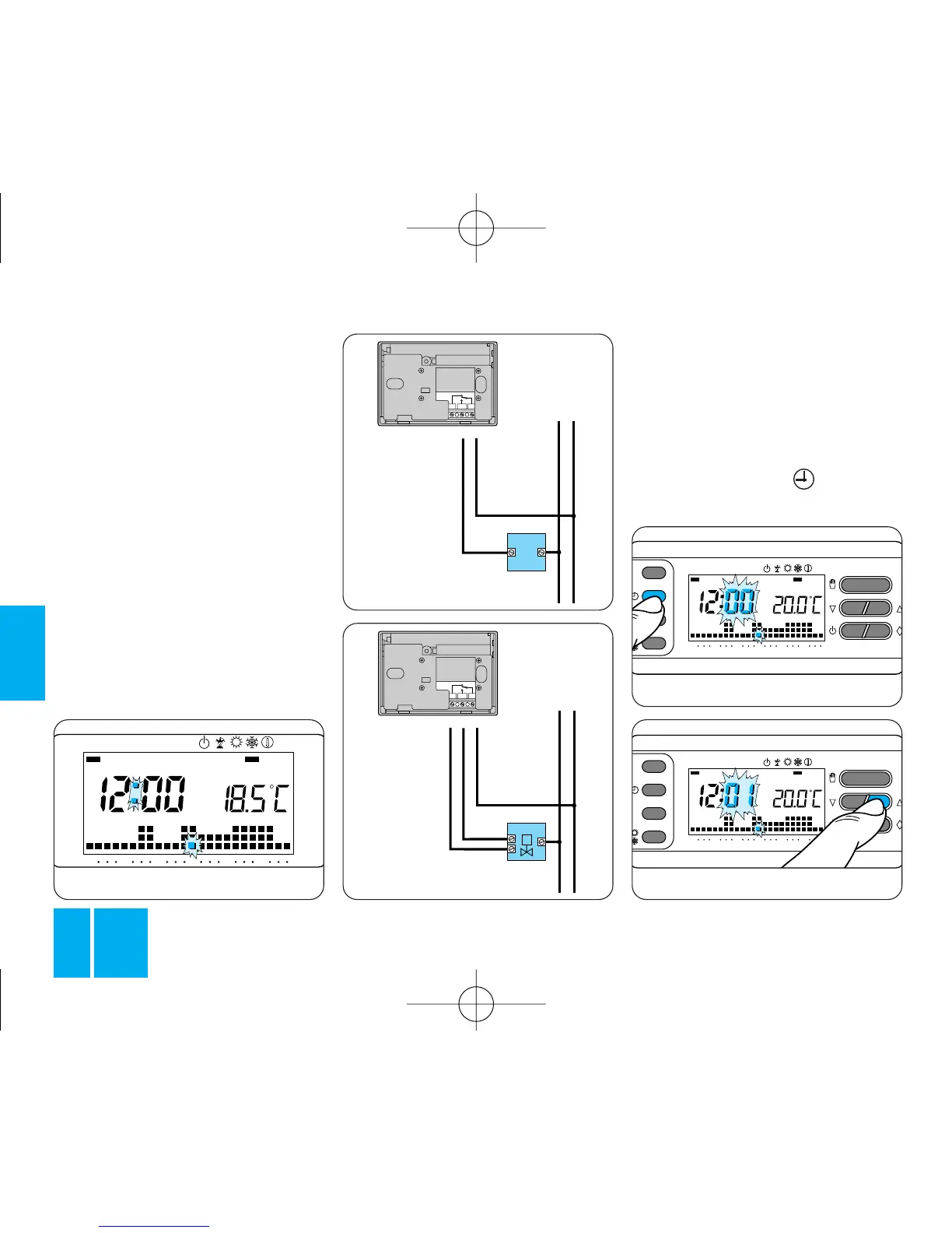
Fig. 15B
OPEN
CLOSED
being controlled by the thermostat;
refer, therefore, to the diagram in
figure 15A or 15B.
KEY
Mains power supply conductors
N = neutral
L = live
Relay conductors
C = common
NA = normally-open contact
NC = normally-closed contact
Loads
U1 = burner, water-circulating
pump, solenoid valve, etc.
LOAD
U2 = motor-driven valve
3 - SETTING
THE CLOCK
3.1 - Open the front panel on the
thermostat.
3.2 - Press button , figure 16.
The minute digits flash.