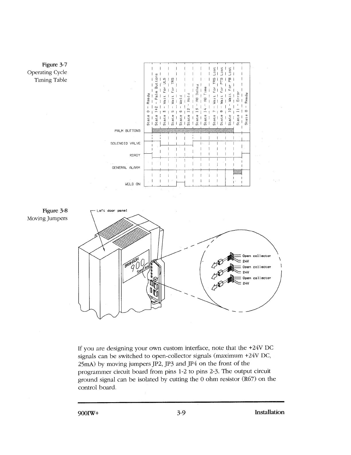
Figure 3-8
Moving Jumpers
Left door panel
Open collector
24V
Open collector
24V
Open collector
24V
Figure 3-7
Operating Cycle
Timing Table
PALM BUTTONS
SOLENOID VALVE
READY
GENERAL ALARM
WELD ON
I
I
;
I ,T I r2
I ~ I
I
I
ro
;
ro
3 3
co
I
'
,;;; ;
Sta
te
70 -
Wa
it
for
PB Los
t
Sta
te
0
-
Rea
dy
If you are designing your own custom interface, note that the +24V DC
signals can be switched to open-collector signals (maximum +24V DC,
25mA) by moving jumpers JP2, JP3 and JP4 on the front of the
programmer circuit board from pins 1-2 to pins 2-3. The output circuit
ground signal can be isolated by cutting the 0 ohm resistor (R67) on the
control board.
900IW+
3-9
Installation
 Loading...