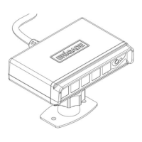
3.2 Installation Site
The installation site must be larger than the detection range of the intended Backsense
®
System and should be relatively flat without excessive deviation. This will allow for basic
setup, configuration, and testing of the Backsense
®
system.
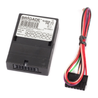
3.3 Electrical Connections
Refer to the vehicle manufacturer or bodybuilder guidelines for installation procedures and
connectivity in all applications. Ensure the positive supply connections are fused at the source.
The system connections are shown in the table below:
• Red cable to non-permanent power supply e.g., ignition.
• Black cable to ground.
• Grey cable to the activating trigger, e.g., reverse. This Activation Input changes the
system status between standby and active.
• White cable is a trigger output to activate secondary functions or devices. The white cable
is switched to ground (black cable) when an object is detected within the detection area.
For example, a secondary device could be a Brigade bbs-tek
®
white sound
®
alarm or a
light beacon to send a warning into the detection area. Simply connect the device to the
same non-permanent power supply as the red cable is connected to and use the white
cable as a negative connection. For electrical loading limits see section “6 Specifications”.
On the BS-8100 system, the distance when the trigger output is activated can be
configured.
Trigger from vehicle, high active
(Range above +9Vdc, up to supply voltage)