Brivo ACS Installation Manual ACS5000-E
ENG-WI-001 © 2005 Brivo Systems, LLC. All rights reserved. Page 20
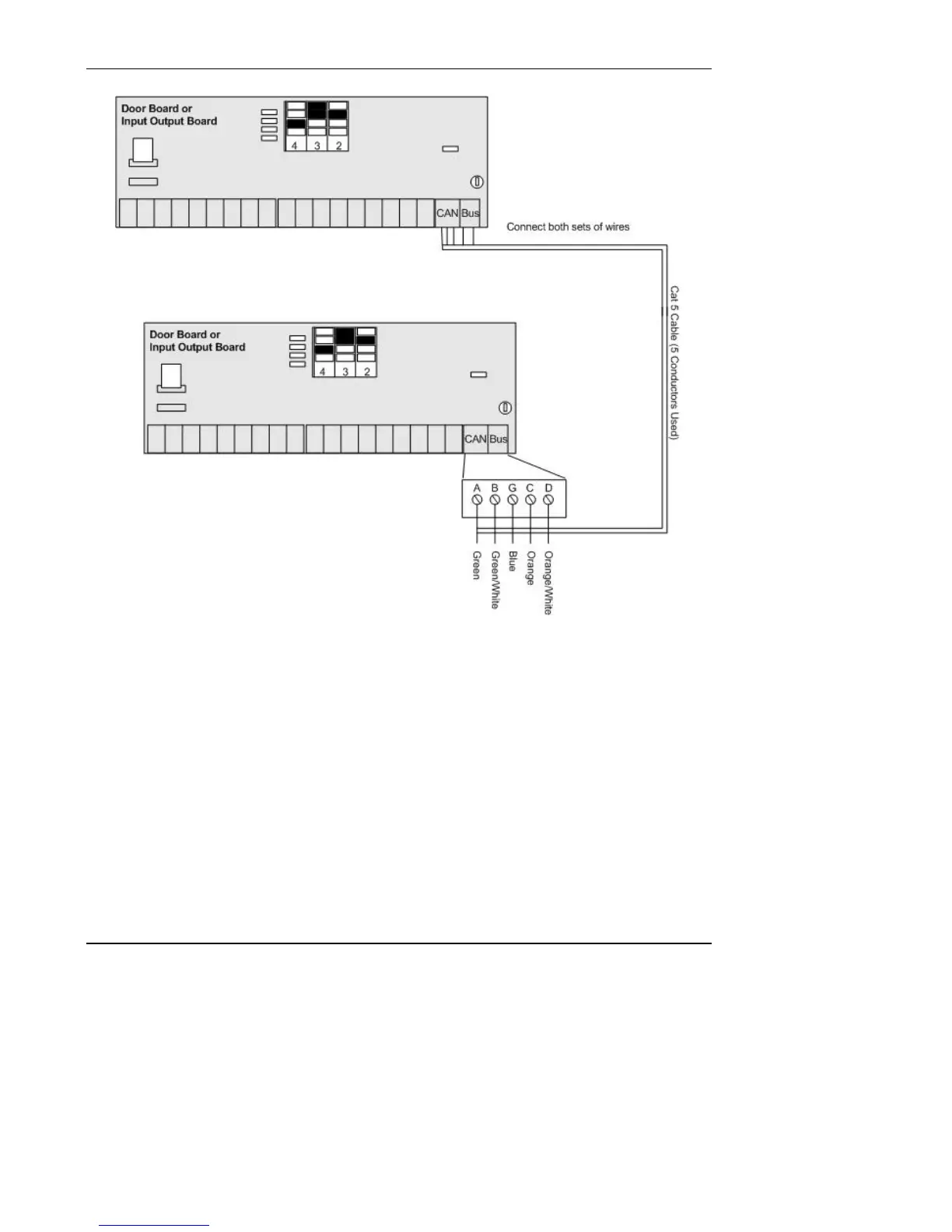
Figure 10. Connect Expansion Boards in Expansion Chassis
3. Daisy-chain the complete set of chassis together.
a) For example, if there are six boards in the control panel, there would be a MAIN
BOARD and five expansion boards (E1, E2, E3, E4, and E5). Each expansion
board could be either a DOOR BOARD or an INPUT OUTPUT BOARD.
b) To daisy-chain the boards together: (See Figure 11 below.)
• Wire E5 to E4 in Expansion Chassis 2.
• Wire E4 in Expansion Chassis 2 to E3 in Expansion Chassis 1.
• Wire E3 to E2 in Expansion Chassis 1.
• Wire E2 in Expansion Chassis 1 to E1 in the Control Chassis.
• Wire E1 to the MAIN BOARD.