Bronkhorst®
Instruction Manual EL-FLOW® Select9.17.099F 27
Changing network settings
· By briefly pressing the switch 5 times with intervals of up to 1 second in normal operation mode, the instrument enters a
state in which the node address and baud rate can be changed (non-Ethernet based protocols only; for Ethernet based
protocols (EtherCAT®, PROFINET), network parameters are configured by the fieldbus master and cannot be set on the
instrument).
· Changing network parameters with the multifunctional switch is done in 3 steps, each represented by a LED indication
pattern (see table below).
· At the start of each step, the according LED(s) start(s) flashing fast (0.1 second on, 0.1 second off). By pressing and holding
the switch, the associated action is started and the flashing slows (05. seconds on, 0.5 seconds off).
set units of node address
Green and red
(simultaneous)
set baud rate index (number of flashes)
*) maximum count depends on the supported baud rates of the fieldbus. See the baud rate table above for supported baud
rates and associated indexes.
To execute a step, follow these instructions:
· Press and hold the switch (flashing slows)
· To select value 0 (zero), release the switch within 1 second, otherwise:
· Count the number of LED flashes
· Release the switch as soon as the required value is reached
· In case you lose count, keep the switch pressed and wait until the flash count reaches its maximum and restarts
On completion of a step, the instrument automatically advances to the next step. When all required steps have been
completed, the instrument returns to its normal operation mode.
If the switch is not pressed within 60 seconds after starting a step, all changes in the previous steps are cancelled and the
instrument returns to its normal operation mode.
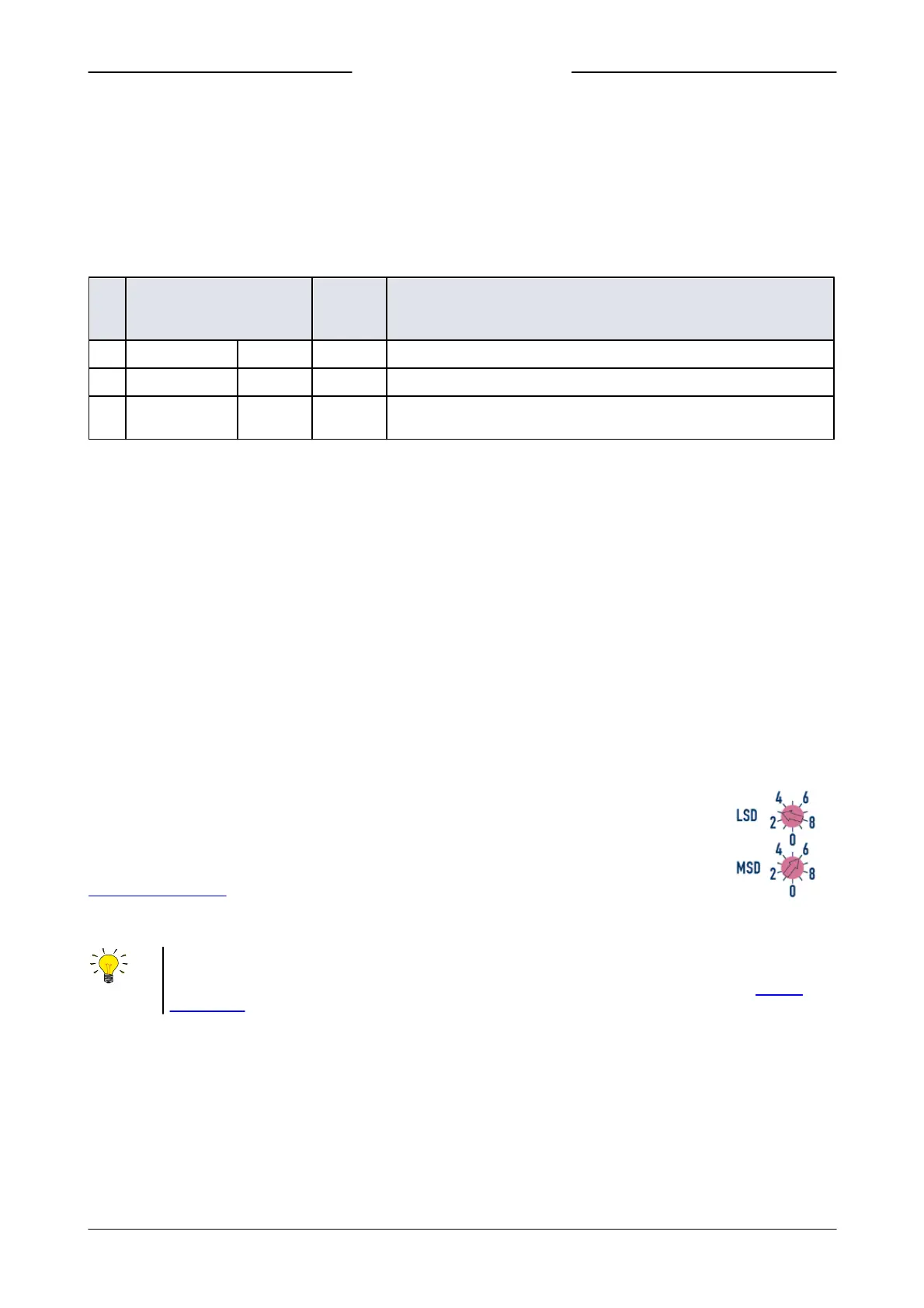
3.5.3 Rotary switches
If the instrument is equipped with a fieldbus interface, it also has 2 or 3 rotary switches (depending on the specific interface
type).
Using the MSD and LSD switches, the required node address of the instrument can be selected, in the
range from 1 to 99. MSD (Most Significant Digit) sets the tens, LSD (Least Significant Digit) sets the units;
in the image to the right the address is set to 63 (note that the actual appearance and orientation of the
switches can differ from the image).
If both switches are set to 0, the node address is set by the according digital parameter (see section
Network configuration).
The switches can be adjusted using a small flat blade screwdriver.
On FLOW-BUS and Modbus instruments, the rotary switches only set the node address for communication through the
dedicated fieldbus connector (if present). If the instrument is configured for RS485 communication (FLOW-BUS or Modbus)
through the 9-pin D-sub connector, use the appropriate digital parameter to set the node address (see section Network
configuration).