3-3
GF Series
Installation and Operation Manual
X-TMF-GF Series-MFC-eng
Part Number: 541B137AAG
March, 2010
Section 3 Installation Instructions
3-4 Unpack and Inspect the GF1xx
Carefully remove the GF1XX from shipping container and verify that the
GF1XX was not damaged during shipment. Notify the shipper immediately
if damage has occurred. Refer to the nameplate on the GF1XX to verify
that the model description is correct.
All products returned must have an assigned Returned Material
Authorization (RMA) number before they are shipped back to the factory.
Refer to Section 8 for further details.
3-5 Position and Mount the GF1XX
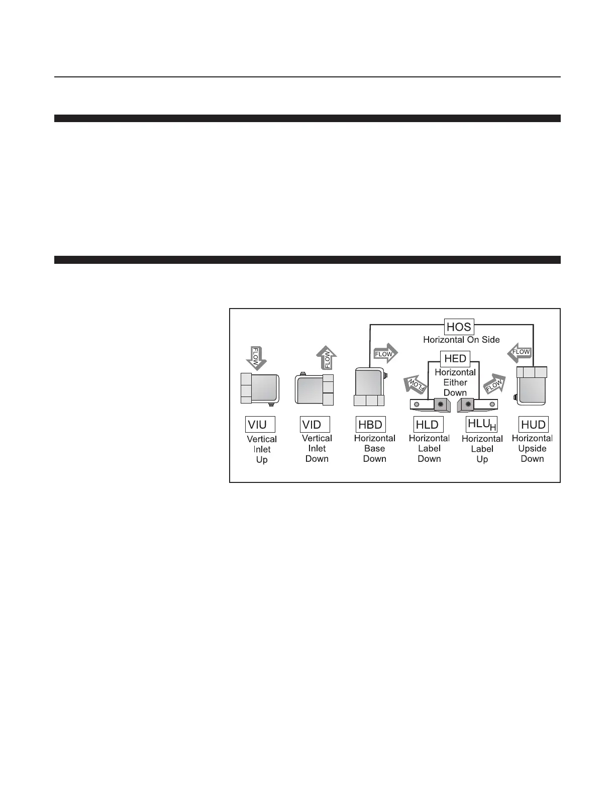
Position the GF1XX so that the gas flow is pointed in the direction of the
grey arrow on the GF1XX label. The various mounting positions are
described in Figure 3-3
The standard orientation for the GF1XX is Horizontal Base Down (HBD).
The GF125 employs a proprietary algorithm that utilizes the internal
pressure sensor to compensate for potential orientation effects when the
MFC is used with certain higher density gases. Non HBD mounting
orientations can be selected by using the MultiFlo software.
In the case of the GF100/120 Series, which does not have an internal
pressure sensor, it is recommended that the MFC is re-zeroed with
process gas following the recommended Brooks procedure (see zeroing
bulletin FSB-001-0015 for futher information).
If your GF1XX is configured with downported fittings, follow Steps 1 though
4 below. If your GF1XX has VCR fittings, proceed to Step 5.
1. Refer to Figure 3-4. If downported fittings (1) are used, the GF1XX is
mounted to K1 Series substrate blocks (2) with four screws (3). Metal
C-seals or W-seals (4) (as provided by integrator) are inserted between
the GF1XX and substrate blocks before the screws are installed. These
metal seals must be replaced after each installation.
Figure 3-3 GF1XX Mounting Attitude Positions
 Loading...
