1-9
Section 1 Introduction
Models MT 3809 & 3819
Installation and Operation Manual
X-VA-MT3809-3819-eng
Part Number: 541B049AHG
September, 2008
Non-Incendive
United States and Canada UL Listed, E73889, Vol. 1, Sect. 15
Class I, II, III, Division 2, Groups A, B, C,D F, and G; T4
Europe – KEMA 01ATEX1236
II 3 G EEx nA II T4
II 3 D T135
o
C
Explosion- proof/ Flame-proof
United States and Canada UL Listed, E73889, Vol. 1, Sect. 14
Class I, Division 1, Groups C, D;
Dust Ignition-proof, Class II, Division 1, Groups E, F, G; Class III; T4
Europe – KEMA 01ATEX2207 X
II 2 G EEx d IIB T4
II 2 D T135
o
C
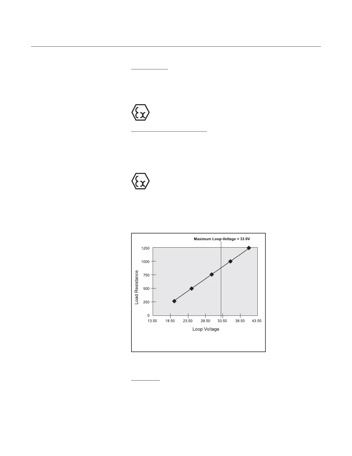
Power Supply and Maximum Load Resistance
21.0 to 33.5 Vdc Power Supply, refer to Figure 1-2 below.
Input Power: Derived from Analog Output
(2-wire current loop transmitter)
Output Signals
Transmitter: 4-20 mA analog output with HART
Update Rate: 4 times per sec.
Range: 3.8 to 22.0 mA
Figure 1-2 Power Supply vs. Maximum Load Resistance
Note: Load resistance should also include I.S. barrier
resistance. When using Model 275 HART Communicator the
minimum load resistance is 250 ohms.
 Loading...


