Operation & Installation Manual RFS1 V2
MA365 Rev 3
17 of 46
3.2.2 Operator Module
The Remote Keypad (BARFS1-RKP) shown in Figure 5 above allows the occupant
to monitor the status of RFS1 V2 system and provides the necessary indicators and
controls to operate the system. Two operator modules can be connected to the
control panel. These should be placed in a convenient location at least one of which
should be a normally occupied area. In the case of a two-storey dwelling one module
could be placed on each level.
3.3 RFS1 V2 Compatible Equipment
3.3.1 New Smoke / Heat Alarms
Smoke / Heat Alarm Part No
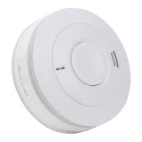
Photoelectric Smoke Alarm for Residential Panels EIB650iWX
Heat Alarm for Residential Panels EIB603CX
3.3.2 Other Equipment
External Compatible Equipment Part No
Remote Second keypad BARFS11-KPAD
Bellow Shaker (Vibration Patrice) EIB207V
Generic Input / Output Module EIB209IO
Ceiling / wall mounting Visual Alarm Device BVADC / BVADW
RED MCP C/W RES.+ BB RESET + BROOKS GLASS MRCSRR
3.4 Power Supply
The primary and standby supplies are calculated to suit the system alarm and
standby requirements. If the primary power supply fails, the secondary supply will
provide sufficient current to maintain the system fully operational for a period
determined by the number of Alarms fitted and the added options to the system.
A battery capacity calculation of RFS1 V2 with all the Smoke / Heat Alarms and
ancillary devices must be carried out as per Chapter 9 page 37 to determine the
battery size. Up to two 7AH or 9AH in Parallel may be required to meet the
requirements of AS3786.
3.4.1 Primary Power Supply / Battery Charger
The primary power supply for RFS1 V2 is fully regulated switch mode power supply
15V
DC / 50W. Nominal output is adjusted to 14.5VDC (13.8VDC on the battery
terminals), maximum current 3.4A @ 14.5V. The power supply is capable of
supplying the max. alarm current required by the RFS1 system without relying on
battery.
Note: Power supply voltage output can be adjusted (if required) to the nominal
voltage using a potentiometer on the power supply PCB. Maximum constant
charging current is 300-400 mA
3.4.2 Standby Supply
Battery capacity is calculated to suit the system requirement
2
. The standard RFS1
V2 can be fitted with 7 or 9 AH battery, if required, additional battery can be fitted
2
See battery capacity calculation sheet Chapter 9