Operation & Installation Manual RFS1 V2
MA365 Rev 3
24 of 46
To install EIB650iWX or EIB603CX, the following procedures can be used:
1) Before installing EIB650iWX or EIB603CX to the zone, ensure the panel is
fully switched off and the panel battery is disconnected.
2) Mount the interface card base assembly BAX16 to the ceiling and terminate
the field wiring according to the panel drawings shown in the Block Wiring
Diagram in Figure 18 page 38.
Note: Interconnect IN / OUT must be terminated correctly i.e. from RFP to IN and
OUT to the next BAX16 and so on. If IN / OUT are swapped, a fault will be generated.
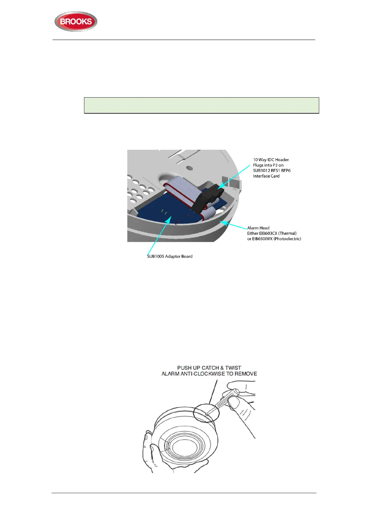
3) Connect the appropriate Smoke/ Heat Alarm head to BAX16 by plugging the
adapter board SUB1005 into the socket in the Alarm as shown in Figure 10.
Refer to Figure 11 for head removal.
•
Figure 10 Ribbon cable from SUB1005
4) Select the DIP switch settings (see Table 6 on page 25) before powering the
panel ON.
5) The panel should initialise and maintain in the normal state (Green LED
steadily lit) if everything is connected correctly.
6) If the ribbon cable assembly is disconnected from an Alarm, the panel should
revert into fault state (refer to respective manuals in alarm head for fault
indications) and panel will chirp and also show a fault indication.
7) If ANY changes to the DIP switch settings are to be made while the panel is
operating, please power down the panel first then set DIP switch. The panel
will reinitialise with the new settings.
Figure 11 Removing Alarm Heads from BAX16



 To Next Page