Operation & Installation Manual RFS1 V2
MA365 Rev 3
29 of 46
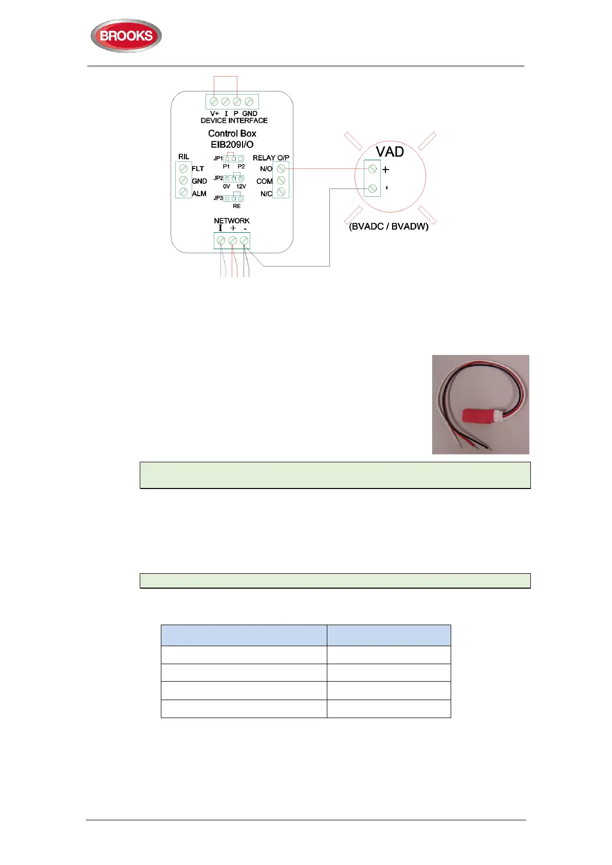
Figure 17 Strobe connection to EIB209IO
Note: JP3 – ‘RE’ = Remote Relay Enable, common interconnect energises the relay
– used for strobe and billow shaker.
4.7 End of Line Setting
The end of line module must be terminated on the last device
on the zone circuit. Only one device required for each RFS1
V2 system. EOL modules can be replaced by setting the DIP
switch no.3 on the interface card SUB1012 to the ON position
as shown in Table 6 page 25.
Note: There should only be one EOL module/device connected in the alarm circuit.
A fault status would be indicated if 2 or more EOL device is detected in the circuit.”.
The EOL module sets the normal operating voltage of the interconnect line. The
voltage of the interconnect input to the main control module determines the three
modes of operation: normal, alarm or fault.
Interconnect Voltage Threshold:
The following voltages can be used to diagnose a faulty system.
Note: Voltage ranges may vary +/-10%
Table 8 Interconnect voltage threshold
Function
Voltage (V
DC
)
Alarm 5.0 ~ 13
Missing Alarm Head fault 2.5 ~ 5.1
EOL (normal) 0.6 ~ 2.5
Open Circuit fault 0.0 ~ 0.6
Colour coding:
Red wire +12 V
DC
Black wire 0 V
DC
White wire interconnect