Operation & Installation Manual RFS1 V2
MA365 Rev 3
23 of 46
Ensure to turn the mains on before connecting the battery
4.2.4 Refit Faceplate
Carefully refit the faceplate to the enclosure by firstly plugging in the 4 way plug to
the connector in the main control module, switch on the mains power and connect
battery leads to battery. Then with the hardware supplied fit the faceplate to the
enclosure.
4.3 Termination of EIB650iWX or EIB603CX Alarms
The new Smoke EIB650iWX and Heat EIB603CX Alarms are to be plugged in the
interface base BAX16 which consists of SUB1012, adapter board SUB1005, ribbon
cable and extended plastic base. Figure 8 below shows the complete BAX16.
Figure 8 Interface Base BAX16
The new interface base BAX16 is connected to EIB650iWX or EIB603CX via the
adapter board and the 10 Way ribbon cable.
The interface card in BAX16 will automatically detect alarm head type of either
EIB650iWX or EIB603CX upon system initialisation and supply the required power
accordingly.
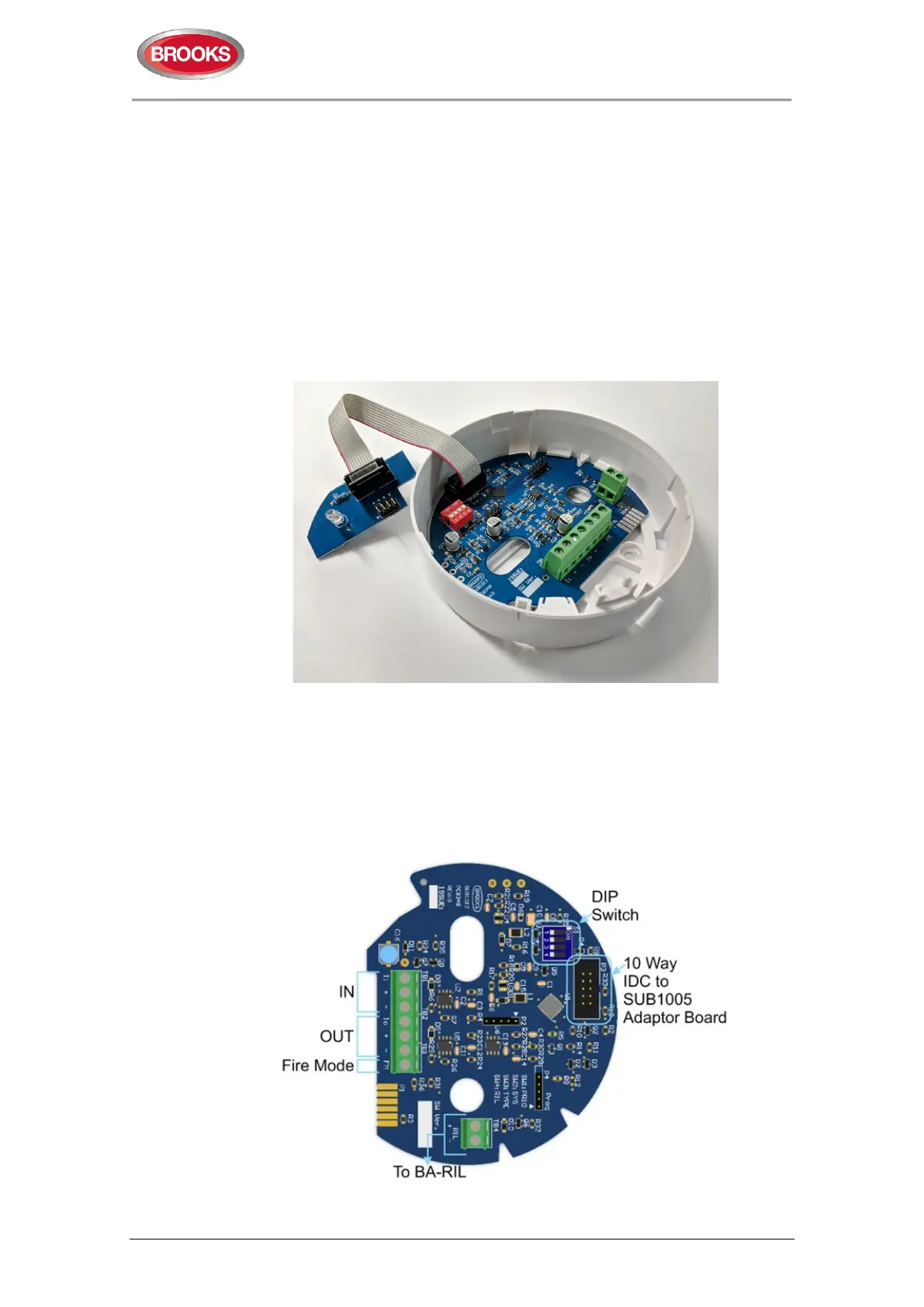
The BAX16 interface and termination board SUB1012 is shown in Figure 9 below.
Figure 9 SUB1012 Terminals
 Loading...