Operation & Installation Manual RFS1 V2
MA365 Rev 3
27 of 46
4.4.2 PCB Layout
AUSTRALIABROOKS
1
1
R4
D6
D5
RELAY O/P
NO COM NC
DEVICE INTERFACE
V+ I P GNDI + -
NETWORK
CON2 CON1
FLT GND ALM
CON3
RIL
CON4
Q4
PCB216R2 SUB873
Z3
D10
D3
D12
D14
R12
JP1
M1 M2
P2
P1
R23
R22
Q2
C11
D13
R10
C7
Z1
R2
D15
Z4
D8
D4
D1
R3
R1
D2
R6
C6
C1
R8
R16
C4
Q1
R21
C3
C5
R15
R17
Q5
JP2
F1
1
JP3
0V
R19
R14
R13
D7
R9
R5
U1
12V
RE
RL1
C10
C2
Z2
R11
D11
D9
R7
REMOTE RELAY ACTIVATION
(VOLTAGE SELECTION FOR
ALARM RELAY
COMMON TERMINAL)
JP2
(ENABLED/DISABLE)
JP3
OTHER ZONE DEVICES
ZONE INTERFACE
(TO MAIN CONTROLLER &
ALARM RELAY
TERMINALS
FAULT & ALARM
LEDs TERMINALS
12V OUTPUT FOR
OPTIONAL DEVICES
e.g VIBRATION PAD,
VADs, ETC
Figure 13 EIB209IO Input / Output Module (SUB873)
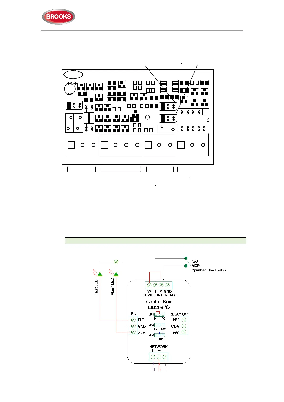
4.4.3 Switch Input Application
The following diagram shows how the module is used as an input module for clean
contact normally open contact such as sprinkler flow switch or manual call point.
Note: Jumper JP1 for selecting priorities is not in use in RFS1 V2
Figure 14 EIB209IO connection to N/O contact sprinkler flow switch input