Installation and Operation Manual
X-TMF-5800S-MFC-eng
PN 541-C-051-AAG
November, 2008
Models 5800-S
12
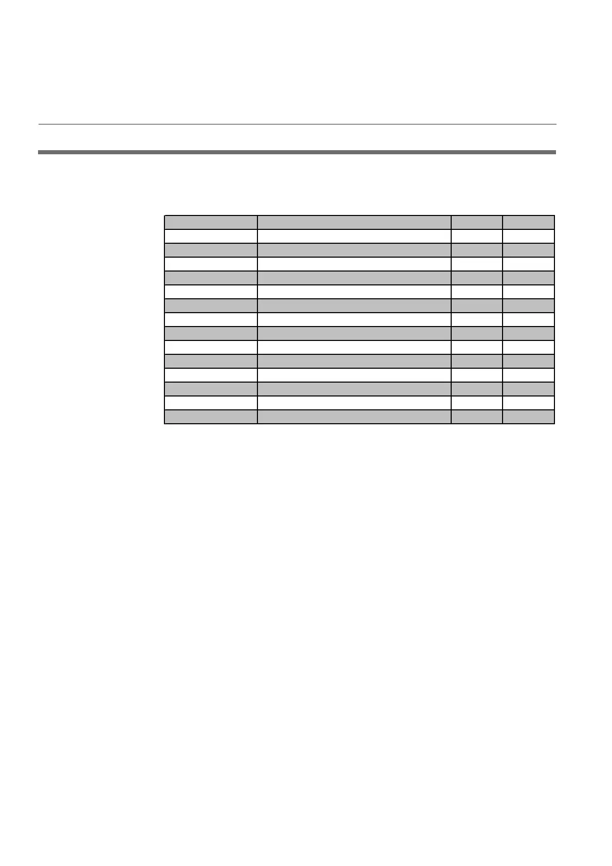
2.8 Electrical Interfacing
The installation of Smart TMF includes a 15-pin Sub-D connector. For details of
correct installation, see Table 2-1
Table 2-1: Electrical interfacing. Smart TMF
Pin (TMF side) Function Controller Meter
1. Setpoint return (-) * n.a.
2. 0 (1)-5 Vdc Flow signal output * *
3. (TTL) Open collector alarm output * *
4. 0 (4)-20 mA Flow signal output * *
5. +15 Vdc to +28 Vdc Power supply * *
6. -15 Vdc Power supply (if required) * *
7. 0 (4)-20 mA Setpoint input (+) * n.a.
8. 0 (1)-5 Vdc Setpoint input (+) * n.a.
9. Power supply common * *
10. Flow signal output common * *
11. +5 Vdc ref. output * n.a.
12. Valve override input * n.a.
13. Not connected * *
14. Optional RS232C-RxD or RS485-A- * *
Signal Output (pins 2, 4 and 10)
Pin 2 indicates the flow rate, represented by a 0-5 Vdc or 1-5 Vdc signal
proportional to the mass flow. Pin 4 indicates the flow rate, represented by
either a 0-20 mA or 4-20 mA signal current proportional to the mass flow. Both
the current and voltage signals are returned via pin 10 on the D-connector.
Analogue Setpoint Input (pins 7/8 and 1; Controller models only) . The Smart
Mass Flow Controller can be used either with a current or voltage Set point. To
use the current Set point, connect the Set point signal to pin 7 and the Set
point return signal to pin 1 on the terminal (jumper J1 must be in place refer to
Figure 2-2). To use the voltage Set point, connect the Set point signal to pin 8
and the Set point return to pin 1 on the D-connector.
5 Vdc reference (pin 11; Controller models only)
A +5 Vdc ref. voltage is available on pin 11. This can be used to set the
Setpoint with the aid of an externally located potentiometer (10 turn 2 KOhm
suggested)..
NOTE: I/O configuration to be defined at time of ordering. Reconfiguration at
customer side can be accomplished using digital communication.
Power Supply
Mass Flow Meter models (pin 5 and 9): The Mass Flow Meter's power
supply is connected via pins 5 (+15 to +28 Vdc) and 9 (power supply common)
on the D-connector.
Mass Flow Controller models (pin 5, 6 and 9): The Mass Flow Controller's
power supply is connected via pin 5 (+15 to +28 Vdc) and 9 (power supply
Section 2: Installation
Artisan Technology Group - Quality Instrumentation ... Guaranteed | (888) 88-SOURCE | www.artisantg.com