Installation and Operation Manual
X-TMF-5800S-MFC-eng
PN 541-C-051-AAG
November, 2008
Models 5800-S
22
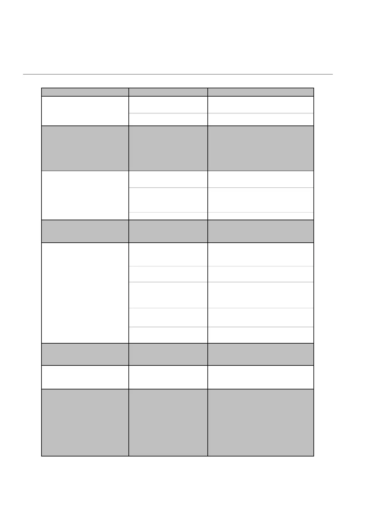
Table 4-1: Troubleshooting
Trouble Possible Cause Check/Corrective Action
Clogged Sensor Clean sensor. Refer to cleaning
procedures (Section 4.3).
Defective electronic board
Clogged Control Valve Clean the control valve (Section 4.3)
or return the device to the factory
Valve override input is
grounded
Check the valve override input
(pin 12)
Defective electronic board Contact Brooks Instrument.
Valve leaks or is stuck
open (applicable to MFC)
Clean and/or adjust control valve
(Section 4.3).
+15V applied to the valve
override input (applicable to
MFC)
Check the valve override terminal
(pin 12)
Defective electronic board Contact Brooks Instrument.
Output signal follows Set point
at higher set points but will not
go below 2%
Control valve leaks or is
stuck open
Clean the control valve or return the
device to the factory (Section 4.3)
Insufficient inlet pressure or
pressure drop
Adjust pressures, inspect in-line
filters and clean/replace as
necessary
Partially clogged sensor Clean sensor, see cleaning
procedures (Section 4.3)
Partially clogged valve
(applicable to MFC)
Clean the control valve (Section 4.3)
or return the device to the factory,
see cleaning procedures
Valve out of adjustment
(applicable to MFC)
Adjust valve, see calibration
procedures (Section 4.4)
Valve guide spring failure
(applicable to MFC)
Controller oscillates (see below)
Instrument grossly out of
calibration. Flow is higher than
desired.
Partially clogged sensor Clean sensor, see cleaning
procedures (Section 4.3)
Instrument grossly out of
calibration. Flow is lower than
desired.
Partially clogged restrictor Replace or clean restrictor.
Pressure drop or inlet
pressure deviates from
calibrated values
Adjust pressures
Oversized orifice Check orifice size
Valve out of adjustment Adjust valve, see calibration
procedures (Section 4.4.)
Unstable inlet pressure Check external pressure regulator
Defective p.c. board Contact Brooks Instrument
Controller oscillates
(applicable to MFC)
Output stays at zero
(regardless of Set point) and
there is flow through the
meter/controller
Flow can not be achieved
regardless of Set point.
(applicable to MFC)
Output signal stays at approx.
5.25 Vdc or 21 mA (regardless
of Set point) and there is flow
through the meter/controller
Output signal follows Set point
at lower set points, but does
not reach full scale
Section 4: Maintenance
Artisan Technology Group - Quality Instrumentation ... Guaranteed | (888) 88-SOURCE | www.artisantg.com