Models 5800-S
Installation and Operation Manual
X-TMF-5800S-MFC-eng
PN 541-C-051-AAG
November, 2008
15
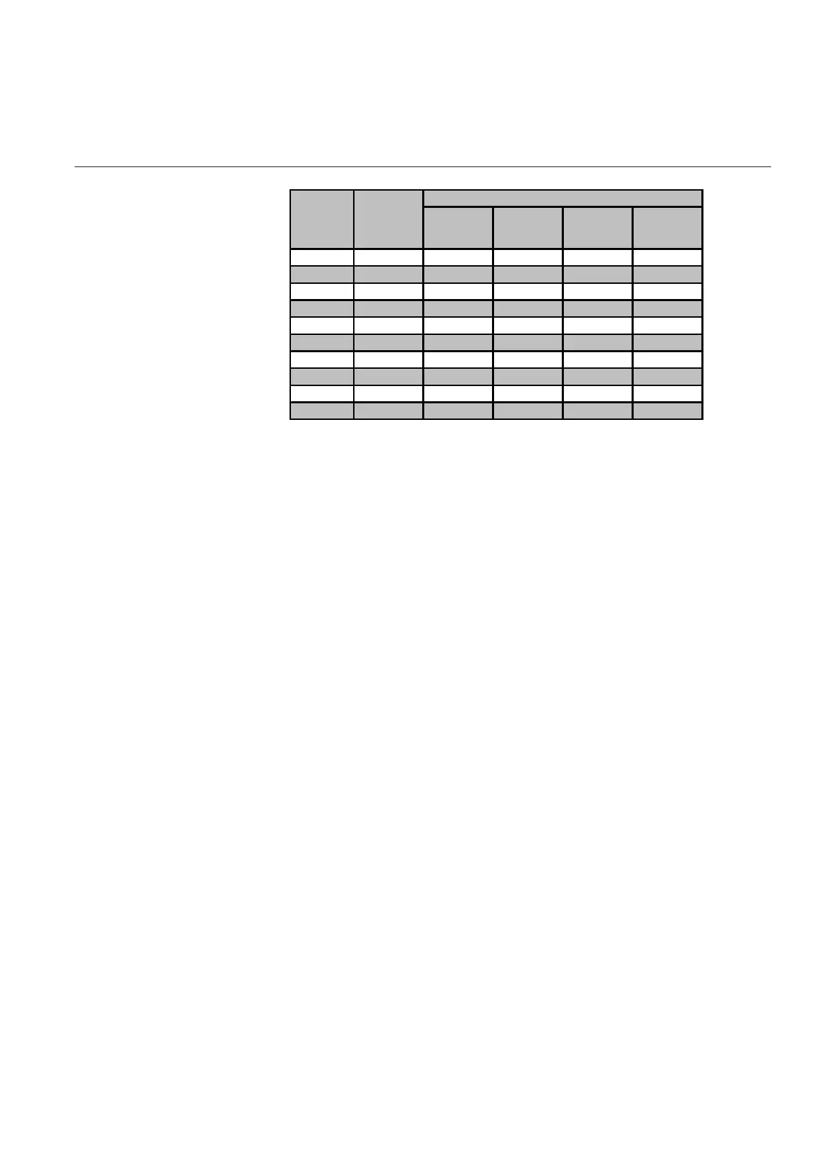
Table 2-2: Dipswitch settings
Switch
#1
Switch
#2
Switch
#3
Switch #4
RS-232 Off
RS-485 On
1200 Off Off Off
2400 On Off Off
3600 Off On Off
4800 On On Off
7200 Off Off On
9600 On Off On
19200 Off On On
38400 On On On
Baud rate
selection
Physical
layer
selection
Dipswitch block SW1
Since Brooks Smart Mass Flow devices are capable of communication
immediately after start-up, you should set the correct baud rates prior to power
up. Any changes to the baud rate settings or the physical layer selection made
during operation will take effect immediately. The communication I/O drivers are
directly connected to the D-connector on top of the device.
The RS-232 is essentially a point-to-point connection, i.e. one host-computer
and one Smart Mass Flow device. Most IBM-compatible PCs are equipped with
one or more RS-232 ports (COM ports) as standard. The RS 232 usage and
definitians are very diverse. On the MF Smart Mass Flow devia the TxD signal is
the output signal of the devia and the RxD the input signal.The communication
terminals can be directly connected to a serial COM-port of any PC. The other
part of the terminals can be connected to Brooks model 0152/0154
Microprocessor-based Read-out and Control Electronics. This model provides
the power supply for Smart Mass Flow devices, as well as providing local
read-out and displaying the analogue output signals. Figure 2-3 shows the
interconnection diagram of the RS-232 configuration. The pin assignment on an
IBM Compatible PC. This is standard for RS-232.
Section 2: Installation
Artisan Technology Group - Quality Instrumentation ... Guaranteed | (888) 88-SOURCE | www.artisantg.com