ADJUSTMENTS
Cut-Off Clutch and Cut–Off Solenoid.
Cut-Off Clutch
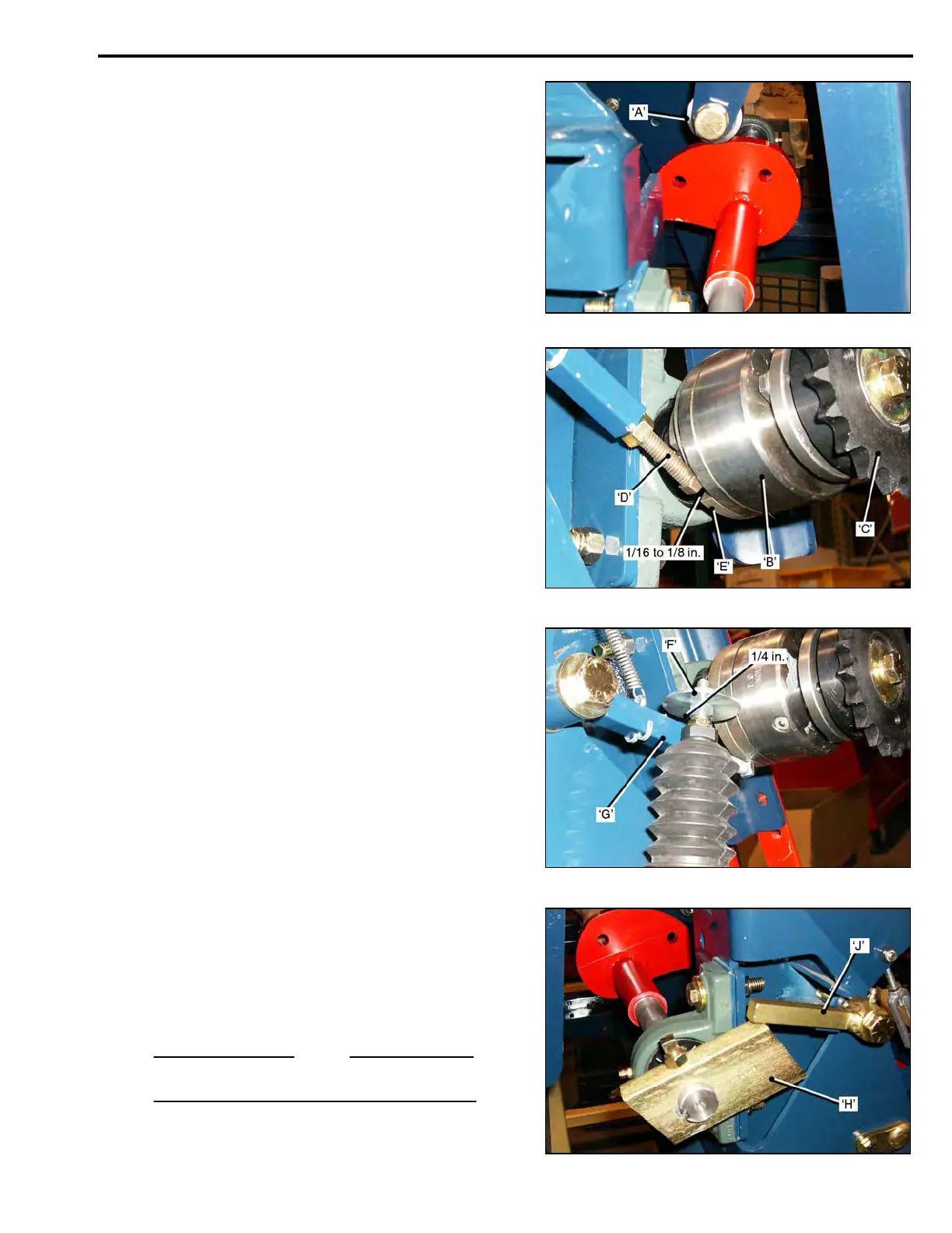
• Rotate the Cut-Off Cam to position the Roller
Bearing ‘A’, in the ‘indent’ on the back of the Cam.
The Blade will be off the ground, in the ’home’ position,
ready for the next cut-off stroke.
• Remove the Cut-Off Drive Chain.
The Clutch ‘B’, will now be disengaged, and the
Sprocket ‘C’, should turn ‘freely’ in both directions.
• Adjustment is made with the Stop Lever Adjusting
Screw ‘D, that engages the Clutch Cam Ring ‘E’.
• If the Clutch does not let the Cam Ring rotate suffic-
ient to allow the Roller Bearing to locate in the Cam
‘indent’, the Adjusting Screw ‘D’, must be ‘shortened’.
• If there is ‘drag’ on the Clutch, or it engages and
disengages while cutting the next roll, the Adjusting
Screw ‘D’, must be ‘lengthened’.
When correctly adjusted, the Cam Ring ‘E’, should be
able to be rotated 1/16 to 1/8 in. away from the head of
the Stop Lever Screw ‘D’.
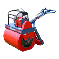
Cut-Off Solenoid.0
When the Solenoid is activated the Large Washer ‘F’,
pulls down the Stop Lever ‘G’, this engages the Clutch,
rotating the Cut-Off Camshaft.
There should be ¼ in. clearance between the Washer
and the Stop Lever.0
Stop Return Cam and Return Cam Stop.
The Stop Return Cam ‘H’, and Return Cam Stop ‘J’,
provide a uniform cut length of the first piece of sod.
When the Stop Return Cam reaches the correct posi-
tion, it is engaged by the Return Cam Stop. This indi-
cates the end of the cut, and prevents spring pressure
on the Cut-Off Frame from rotating the Camshaft
backwards.
NOTE
The Stop Return Cam part number is: 001802.
3-19