2.7 Connecting the test item
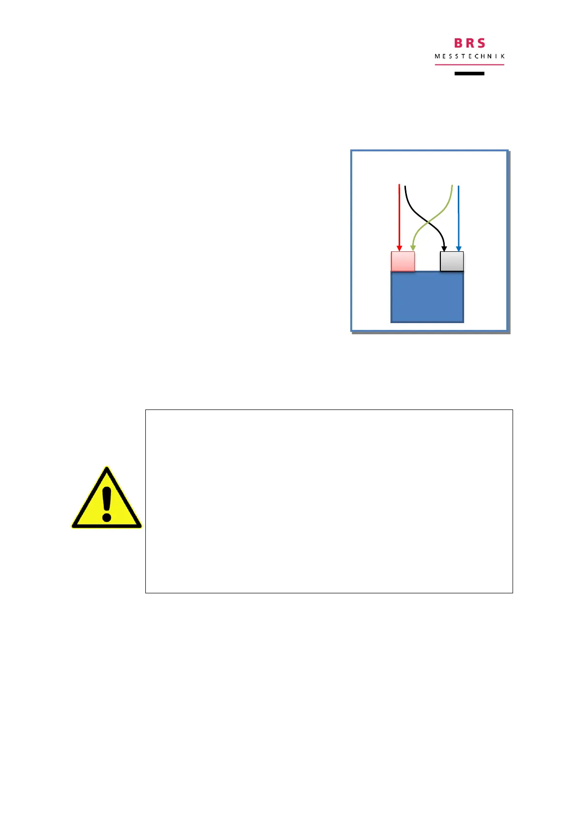
The impedance measurement device works according to the four-conductor principle
(Kelvin connection), and therefore has four connections for measuring impedance:
two connections for feeding in the current (I+ and I-)
and two connections for measuring the voltage (U+
and U-). They are only brought together on the test
item (battery) and connected in pairs (I+ and U+
with the positive pole, I- and U- with the negative
pole).
If the measurement cable is used with the two Kel-
vin clips, this happens automatically because each
clip contains both a current and a voltage connec-
tion.
When using the measurement cable with the four
crocodile clips, two clips must be attached to each
battery pole.
The non-terminated cable provides the greatest degree of freedom, such as the con-
nection of test buttons, screwed together cable lugs or a solder connection. This
sometimes gives more reproducible results
When connecting the measurement conductor, pay attention to the
voltage potential. The device has polarity protection, but the (auto-
matically reset) protection could be activated.
Take care that no high voltages above 60V occur.
Please note that if there is an error when measuring cells in the bat-
tery module, the overall voltage of the battery module may be pre-
sent at the measurement inputs.
Please note that the measurement device discharges the battery and
can therefore completely discharge the battery if it is left to run with-
out any control.
The lower the impedance to be measured, the higher the requirements for the meas-
urement connection. For very low impedances (<1mΩ), special connection might be
advisable - please inquire.
Recommendations for proper wiring can be found in section 10.1.