4 Measurement Functions
4.1 Functional principle of the impedance measurement
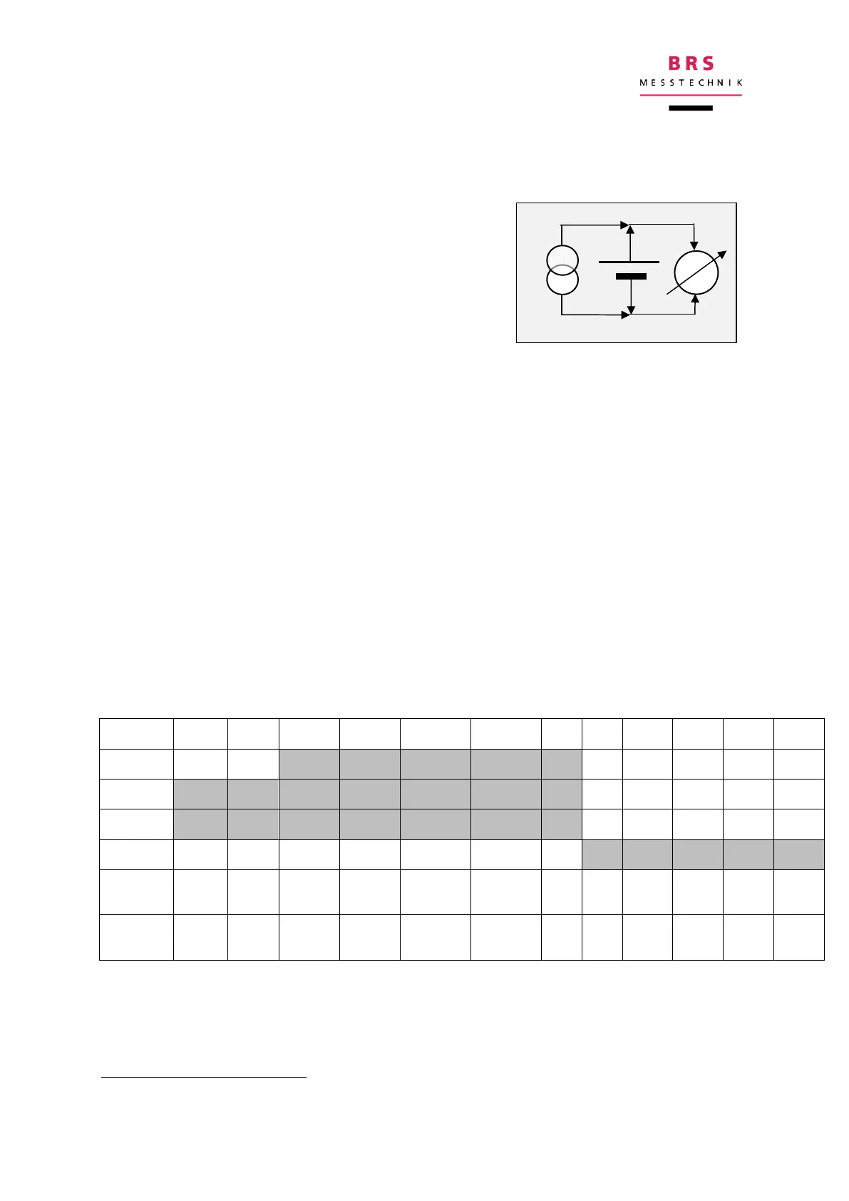
The measurement device loads the battery with
an alternating current (I
AC
) which is considerably
smaller than the load current, and measures the re-
sulting voltage (U
AC
), which is in the mV range.
The measurement of alternating voltage is carried
out selectively and synchronously, with the results
by real part and imaginary part. Dividing the alternat-
ing voltage by the alternating current yields the complex impedance Z
AC
. The real
part represents the ohmic components, the imaginary part represents the capacita-
tive (or inductive) components. A negative imaginary part means capacity, a positive
part means inductance.
4.2 Overview
The device is operated using a graphical user interface (GUI). Settings can be ad-
justed and the results shown using this interface.
All setting and results can also be remote controlled using a proprietary communica-
tion protocol.
4.3 Settings
a) Measurement range
The measurement ranges depend on the instrument version:
If the expected impedance is known, then the closest range can be set. If not, it is
best to start at the highest level (1Ω) and reduce it as necessary.
The 300Ω range can be used up to 500Ω.