11 Appendix
11.1 Recommendations for cable running
The impedance measurement device uses low measurement voltages in the mV
range so that it can work in the linear range of the battery characteristics. Both the
actual measurement device used and the type of connection therefore have an effect
on the measurement quality.
The two connections for the measurement current (I+ and I-) are non-critical and can
be connected to the battery poles in a suitable position using crocodile clips. The
procedure with the voltage connections (U+ and U-) is different: these should be
connected as closely as possible to the battery in order to avoid errors caused by
cable resistance at the battery poles. This is particularly important for test items with
very low resistance (<1mΩ).
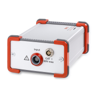
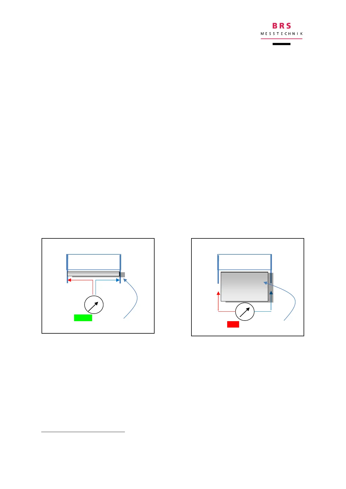
For sensitive measurements, you should also try to minimise interference connec-
tions (e.g. 50Hz mains voltage) in the voltage measurement conductors. It is there-
fore sensible to keep the area enclosed between the two voltage conductors as small
as possible, for example by ensuring that the measurement conductors are kept
twisted for as long as possible and are connected as close to the battery as possi-
ble
:
Take care to avoid cross-coupling of the measurement conductors on the voltage
measurement inputs (U+/U-) by keeping them separate.
11.2 Recommendations for selecting frequencies
The frequency grid contains values of 45,5Hz and 100Hz which are close to mains
frequency. Depending on the environment, measurements at these frequencies may
exhibit higher fluctuations. Therefore, if possible, avoid these frequencies.
In accordance with the law of induction, a magnetic alternating field which cuts across the conductor
loop generates a voltage which is superimposed as an interference voltage.