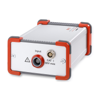
2.4 Connecting the measurement cable for impedance and voltage
On the left-hand front panel there is a measure-
ment socket, to which the measurement cable is
attached. The plug has a push-pull mechanism,
which means it is pushed in until it locks and
pulled out of the plug casing to remove.
There are several types of measurement cable for connecting the test item:
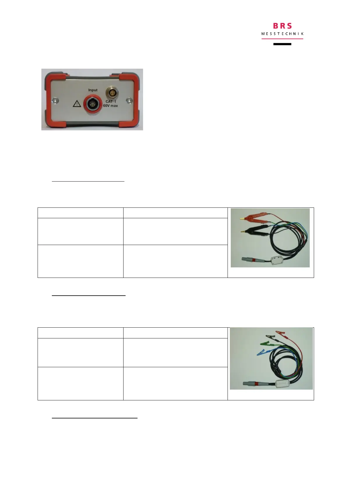
a) MK-S: Standard variant
This measurement cable has two Kelvin clips, which are connected to the two poles
of the test item. It is simple to use and produces good results for most cells.
Colour of the Kelvin clips
Current connection I+
Voltage connection U+
red; the two connections are
guided separately to the collet
jaws
Current connection I-
Voltage connection U-
black; the two connections are
guided separately to the collet
jaws
b) MK-U: Universal variant
For very low ohmic cells (>10Ah, <1mOhm), the use of the cable with four crocodile
clips is recommended, because it can be connected more precisely, but it is also a
little more awkward to use.
Colour of the crocodile clips
Current connection I+
Current connection I-
red (at the + pole)
black (at the – pole)
Voltage connection U+
Voltage connection U-
green (at the + pole)
blue (at the – pole)
c) MK-K: variant for cable lugs
For very low ohmic cells with threaded bolts or female threads. The two lugs per pole
are isolated against each other with an insulating bushing. Available for threads M6,
M8, M10.