40
N150
30
20
I
E
Hand-
Arm
-Uninterrupted
1-----+--+--+--+---+----+---+-----+------½
( Reference Frequency 160 Hz)
15
C0
I
10
0
-140
Whole-Body Exposure
Limit
I
. Ref. Freq.
(az)
4
to
8
Hz
Whole-Body Fatigue
Dec
. Prof. ..
..
(ax
and
ayl
2,8
Hz
N 8
I
p
~4
-~ 3,2
a;
2
oi
8 1,5
,ct
~
1,0
a: 0,8
] 0,5
-g,
0,4
~
0,32
~
0,2
~
0,15
[
0,1
LL
0,08
~
co
:E!.
C
.g 130
~
Q)
oi
0
0
,ct
~
120
a:
]
..c
Ol
~
110
>
0
C
Q)
:::,
[ 100
LL
Whole-Body Reduced Comfort
Motion
Sickness Reduced
Comfort
Reference Frequency 0,36
Hz
I I I I I
0,05
95
1,5-2
-3-4-5
·
6-
8
·10-15-20-25
30 40 50 min-Exposure Time
--+--~~-I
1 min.
0,1h 0,5h
lh
1,5h 2h 3 4 5 6 8
1012
16
2024
791106
Fig.7. Frequency-weighted amplitude versus
time
weighting functions built into the
2512.
The
form
of
the permissible
limit
lines shown are
as
prescribed in the relevant standards and
recommendations and are normalised
to
the reference frequencies indicated
ond
RMS level is
compared
to
the
vi-
bration
level
versus
permissible
ex-
posure
time
relationship
specified
by
the
document
defining
the
hu-
man
vibration
criteria
chosen
.
These
relationships,
which
are
shown
graphically
in
Fig.7
are pre-
programmed
into
a
digital
memory
(ROM)
built
into
the
2512.
The
me-
mory
then
provides
the
permissible
exposure
time
(
Ti)
for
the
two-sec-
ond
RMS level.
The
sum
of
the
indi-
.d I d ·
ti
vI
ua
two-secon
ratios
I:
- . x 1
00%
Tl
is
defined
as
the
"equivalent
expo-
sure"
and
by
definition
must
be
<
100%
to
be
within
the
permissi-
ble
exposure
limit
.
Continuous
sum-
mation
of
these
two-second
doses
to
obtain
the
equivalent
exposure
is
performed
by
the
dose
calculator
which
updates
the
digital
readout
accordingly
every
two
seconds. The
display
is
calibrated
to
indicate
1
00%
when
the
permissible
expo-
sure
limit
is reached.
Leq
Measurement.
Leq
(equiva-
lent
continuous
vibration
level) is a
logarithmic
function
of
the
fre-
quency-weighted
energy
mean
vibra-
tion
level averaged over
the
whole
measuring
period. It can be
consid-
ered as
the
vibration
level
which
would
have
the
same
(frequency
weighted)
vibration
energy
as
the
ac-
tual
fluctuating
vibration
signal
mea-
sured
over
the
same
period
of
time
.
In
the
251
2
the
varying level
of
the
actual
vibration
signal
is
continu-
ously
sampled,
squared,
and
"parked"
in a
digital
memory
. The
L,
eq
calculation
circuitry
continu-
ously
calculates
the
average
of
the
values
accumulated
in
the
memory
from
the
beginning
of
the
measure~
ment
period. A
corrected
averaged
level updates
the
digital
display
every
eight
seconds. The
equivalent
level
obtained
can be . expressed as
follows
:
Tf
( a
(t)
~
?dt
,o-67
0
where
Leq
is in dB re. 1
o-
6
ms-
2
and
a(t) is
frequency
weighted
accel-
eration
in
ms-
2
The
digital
memory
used
to
store
Leq
data can
accommodate
data
from
at
least a
1000
s ("' 1 7
min-
utes)
and
up
to
a
53
minutes
meas-
urement
period
depending
on
the
signal level. A
full
memory
is
indi-
cated by a lamp.
Whole-body
vibration
measured
over a
short
period in
the
Leq
mode
can be
entered
into
the
level-time
curves
shown
in
Fig.7,
to
find
di-
rectly
the
maximum
permissible
ex-
posure
period,
assuming
the
meas-
urement
period
to
be
representa-
tive
.
The
Leq
measurement
mode
is
useful
for
quick-look
measurements
since
the
measuring
period can be
terminated
at
will,
logically
when
the
Leq
reading
has
stabilised
at
an
approximately
steady value. Periodic
readout
and
resetting
of
the
Leq
cal-
culator
can be
performed
automati-
cally
in
conjunction
with
readout
to
the
Alphanumeric
Printer
Type
231
2,
or
other
device
connected
via
the
IEC
compatible
interface
bus.
Triaxial
measurements
are
made
by
sequentially
measuring
Leq in
the
X,
Y
and
Z
directions,
then
taking
the
square
root
.
of
the
sum
of
the
squares
of
the
three
Leq s (in
ms-
2
).
This
will
yield
the
max.
weighted
Leq,
which
can
be
evalu-
ated
with
Fig.
7 .
Peak
Measurement.
A peak
detec-
tor
continuously
monitors
the
fluctu-
ating
vibration
signal and
stores
the
maximum
ievel
which
has
occurred
during
the
measuring
period.
The
maximum
peak level is registered
on
the
digital
readout
in dB re.
1
o-
6
ms-
2
.
It is
generally
recommended
(for
example
in
IS0
'
2631)
that
when
re-
porting
human
vibration
environ-
ments,
the
crest
factor,
that
is
the
peak value
to
rms
value
ratio
of
the
signal,
should
also be
determined
.
This is
simply
calculated,
first
con-
verting
the
peak
and
RMS levels
measured,
to
absolute
values
using
Fig.6
.
Measurement
Period. The period
during
which
the
measurement
and
calculation
circuits
are active is go-
verned
by
the
"Start"
and
"Stop"
buttons
. The elapsed
measurement
time
in
minutes
(resolution
0,
1
min
., 6
s)
may
be displayed.
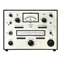
Analogue
Meter
. A
small
moving
coil
meter
mounted
ori
the
front
panel
indicates
the
RMS
level
of
the
filtered
and
rectified
vibration
sig-
nal . It has a scale
calibrated
to
read
in dB re . 1
o-
6
·
ms
-
2
and
in
ms
- 2 . It aids visual
monitoring
of
the
signal level and can be used
for
unit
conversion
between
the
two
scales.
When
switched
to
measure
hand-arm
vibration
,
20
dB (x 1 0)
should
be added
to
the
indicated
le-
vel.
Overload Indicators
Three
light
emitting
diode (LED)
lamps
mounted
adjacent
to
the
"Dis-
play
Mode"
switch
indicate
various
overload
conditions
so
that
false
measurements
can be avoided. The
Eq
. Exp . LED
lamp
lights
when
the
equivalent
exposure
"do
"
s~"
e_xceeds
9999%
. It also
indicates
when
the
5

 Loading...