FIGURE THREE
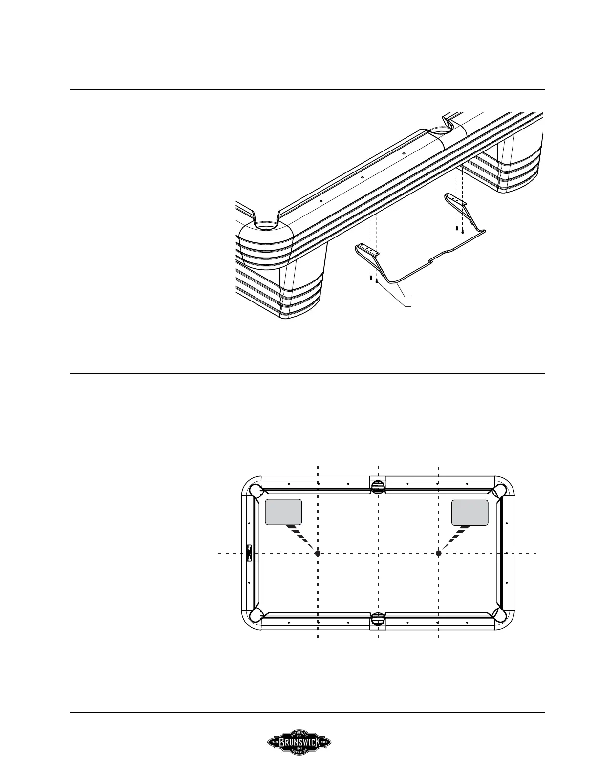
Step #5: Attach one bridge rack to the bottom edge of both side sills using
#8 x 1-1/4 pan head screws. Attach utilizing the pre-drilled holes at the
center of each side sill bottom edge. Use the forward most hole pattern
in the bridge rack brackets for this application.
BRUNSWICK INSTALLATION MANUALPAGE 15
FIGURE THREE
FIGURE FOUR
POCKET, STORAGE BOX, TRIANGLE RACKS,
BRIDGE RACK AND BED SPOT ASSEMBLY
FIGURE FOUR
Step #6: Locate and apply the foot end bed spot. Bed spot is to be aligned
with the center rail sight in each rail and the center sight of side rail on the
foot end of the table. (Head bed spot optional and located in the same
manner)
#8 x 1-1/4 PAN HEAD SCREW
BRIDGE RACK
HEAD
SPOT
FOOT
SPOT
CENTENNIAL