FIGURE THREE
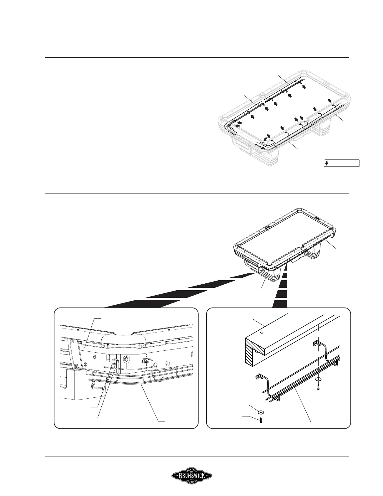
Step #3: Working from the foot end of the table, place the foot end gully
track assemblies. One side at a time, insert the end through the opening
in the receiver box assembly. Hold the track assembly in place, making
sure all hanger brackets are up against the base frame, and attach using
#10 x 1-1/4 pan head screws and #10 fender washers.
BRUNSWICK INSTALLATION MANUALPAGE 17
FIGURE THREE
FIGURE FOUR
GULLY VERSION ASSEMBLY CONTINUED
FIGURE FOUR
Step #4: Attach both head end gully track assemblies utilizing the same
hardware. Hold track assemblies in place, making sure all hanger brackets
are up against the base frame and side pocket ends are touching the foot
end track assemblies leaving no gap.
LH FOOT
GULLY TRACK
LH HEAD
GULLY TRACK
= ATTACH POINT
CENTENNIAL
RH FOOT
GULLY TRACK
RH HEAD
GULLY TRACK
LH HEAD
GULLY TRACK
LH FOOT GULLY TRACK
GULLY TRACK
BASE FRAME
#10 FENDER
WASHER
#10 x 1-1/4 PAN
HEAD SCREW
BASE FRAME
#10 FENDER
WASHER
#10 x 1-1/4 PAN
HEAD SCREW
GULLY TRACK