Quick Reference Guide QRG
1
Symbol Sensor 1 (software limit switch 1)
2
Symbol Servo-center position
3
Symbol Sensor 2 (software limit switch 2)
4
Set position for software limit switch 1
5
Set servo-center position
6
Set position for software limit switch 2
7
Actual position of the actuator (grapfical display)
8
Actual position of the actuator (numerical display)
When the controller is delivered the position for software
limit switch 1 will display “-2048“ and the position for
software limit switch 2 will display “2047“.
The factory default settings will be overwritten by the new
settings when teach-in is run.
The relevant symbol (sensor 1, sensor 2 or servo-center
position) will be displayed as inverted after the teach-in of
a new setting has been run.
Inverted symbol display
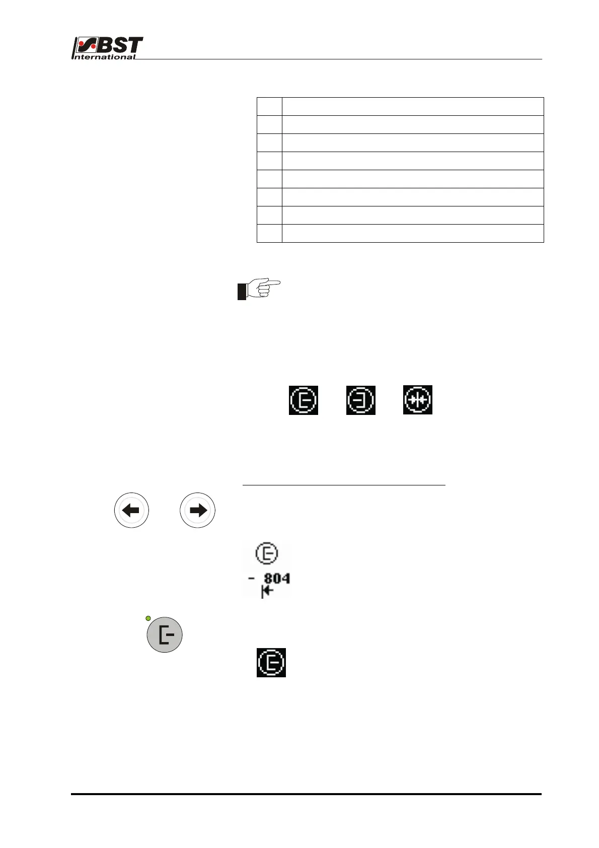
Step 2: Set position for software limit switch 1
5. Move guiding device to the desired position for software limit
switch 1 (towards sensor 1) using the arrow keys.
or
The position indicator for software limit switch 1
shows the actual value supplied by the position
feedback of the actuator.
Range of values: -2048 … +2047.
6. Press key Sensor 1.
The position for software limit switch 1 is stored.
The symbol “sensor 1“ is represented inversely.
Quick Reference Guide EDV no.: MD.341.01.01
ekr 500 Plus with CLS Pro 600 Issue Date: 31.03.2009 Page: 9/18

 Loading...
