5
Electrical Connection
14/45 ekr 500 digital Unit Touch – Master-Slave Guiding with Sensor Positioner
5.2 Fitting the Cable Connections
5.2.1 Required Accessories
For connecting the edge sensors to the ekr 500 digital Unit Touch
web guiding controller you need optional extension cables.
Only original accessory components from BST may be used.
Neglecting this information leads to warranty claims being invalid-
ated.
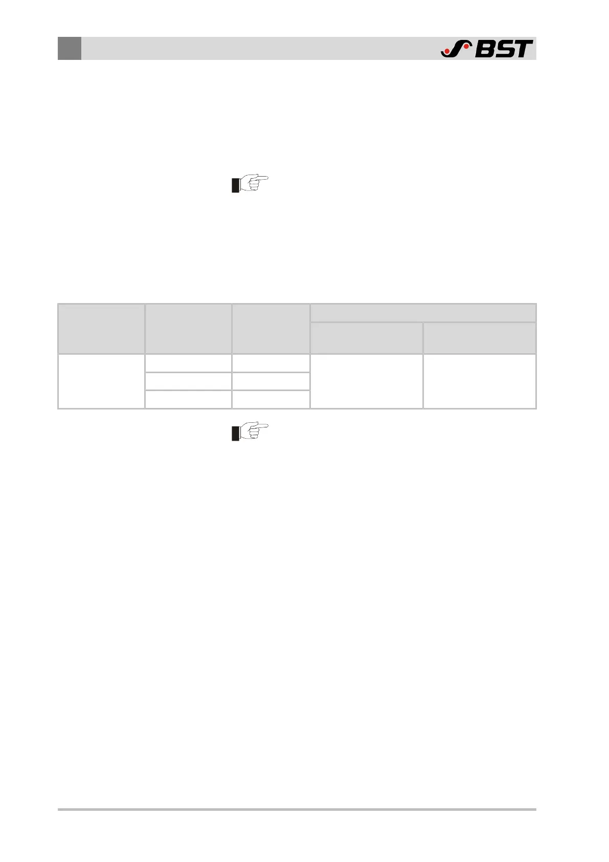
The number and length of the required extension cables depends
on the number of edge sensors used and on the distances to the
web guiding controller. The table specifies the respective minimum
amounts required.
Accessory Part Length Order Number Amount Required
Master-Slave Guiding
with Two Edge Sensors
Master-Slave Guiding
with Four Edge Sensors
Extension cable
2 m 131993
2 45 m 131994
10 m 131995
It is also possible to combine cable extensions of different
lengths. However, the maximum permitted total length of
20m of the connecting cable must never be exceeded!
5.2.2 Wiring Diagrams
You will find wiring diagrams for the following Master-Slave Guiding
types in the appendix of this document:
Master-Slave Guiding with two edge sensors
■ Guiding to the left web edge
■ Guiding to the right web edge
Master-Slave Guiding with four edge sensors
■ Web edge and web center-line guiding
 Loading...


