7
Operation
34/45 ekr 500 digital Unit Touch – Master-Slave Guiding with Sensor Positioner
7.3 Operation Display
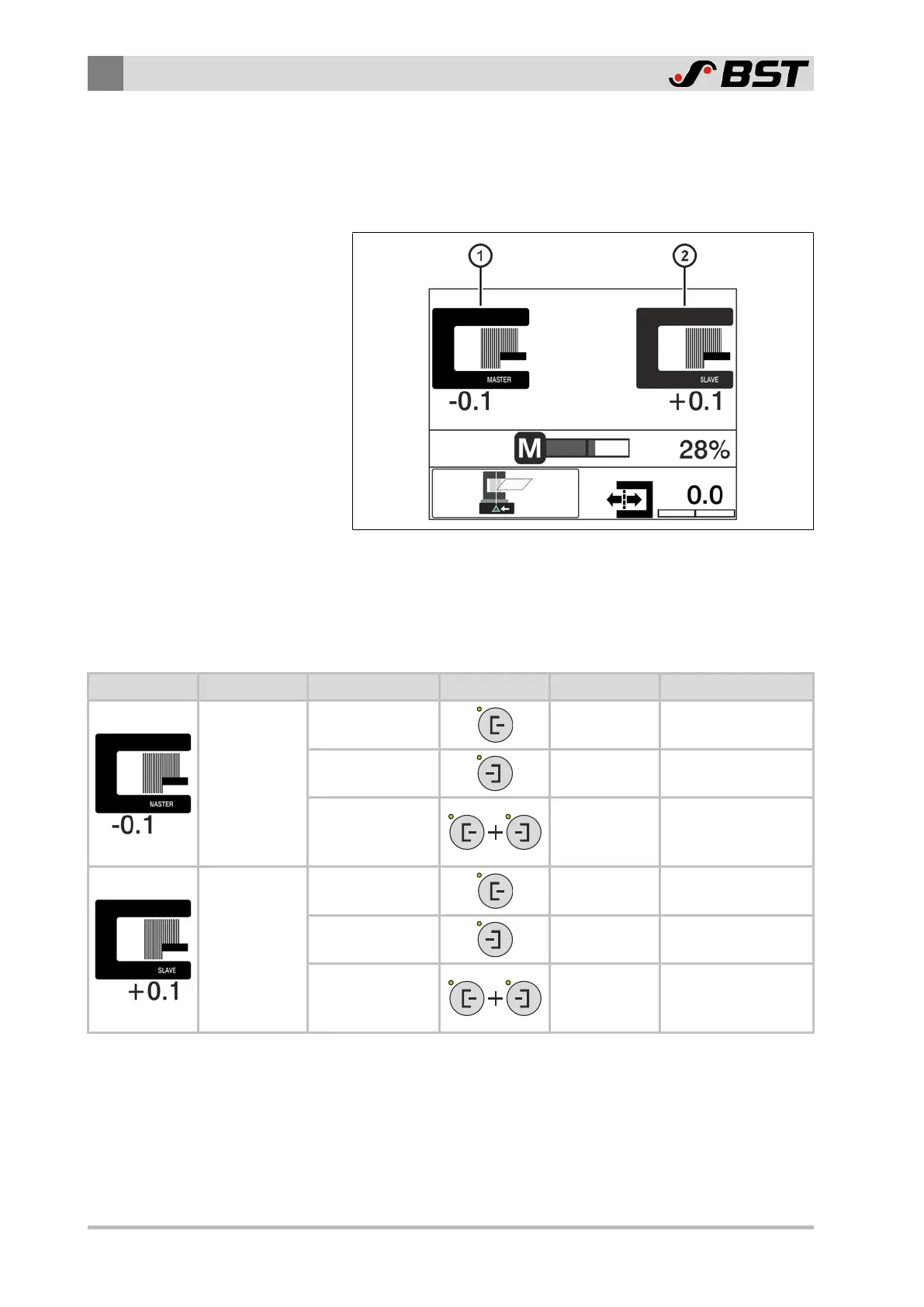
If the Master-Slave guiding is active, the two sensor symbols in the
operation display of the controller show the position of the
MASTER and of the SLAVE web.
Fig.12: Operation display when Master-Slave guiding is active
①
Position display MASTER web
②
Position display SLAVE web
The position displayed depends on the selected guiding mode.
Sensor Symbol Material Web Guiding Mode Key(s) Edge Sensor Position Displayed
MASTER web
Guiding to the
left web edge
Sensor3 Left web edge
Guiding to the
right web edge
Sensor4 Right web edge
Web center-line
guiding
Sensor3
&
Sensor4
Web center-line
SLAVE web
Guiding to the
left web edge
Sensor1 Left web edge
Guiding to the
right web edge
Sensor2 Right web edge
Web center-line
guiding
Sensor1
&
Sensor2
Web center-line

 Loading...


