EasyManuals Logo

BST ekr 500 digital Unit Touch User Manual

BST ekr 500 digital Unit Touch
45 pages
To Next Page IconTo Next Page
To Previous Page IconTo Previous Page
Page #41 background imageLoading...
Page #41 background image
Wiring Diagrams
A
ekr 500 digital Unit Touch – Master-Slave Guiding with Sensor Positioner 41/45
A Wiring Diagrams
A1 Master-Slave Guiding (Web Edge Guiding)
A1.1 Guiding to the Left Web Edge
Connecting cable
3 m (118 447)
5 m (118 448)
10 m (118 449)
Control panel
ekr commander
Controller
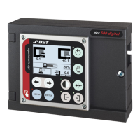
ekr 500 digital Unit Touch
Connector assignment
with two edge sensors
ekr commander: X101
Sensor 1: X102
Sensor 3: X100
Sensor 3
Sensor Positioner
Actuator
MASTER web
(unguided)
SLAVE web
(guided)
Guiding
device
Sensor 1
Extension cable
2 m (131 993)
5 m (131 994)
10 m (131 995)
Fig.14: Wiring diagram for master-slave guiding with two edge sensors (guiding to the left web edge)

Table of Contents

Other manuals for BST ekr 500 digital Unit Touch

Questions and Answers:

Question and Answer IconNeed help?

Do you have a question about the BST ekr 500 digital Unit Touch and is the answer not in the manual?

BST ekr 500 digital Unit Touch Specifications

General IconGeneral
BrandBST
Modelekr 500 digital Unit Touch
CategoryController
LanguageEnglish

Related product manuals