Manual EVOTOUCH v.5 76 / 104
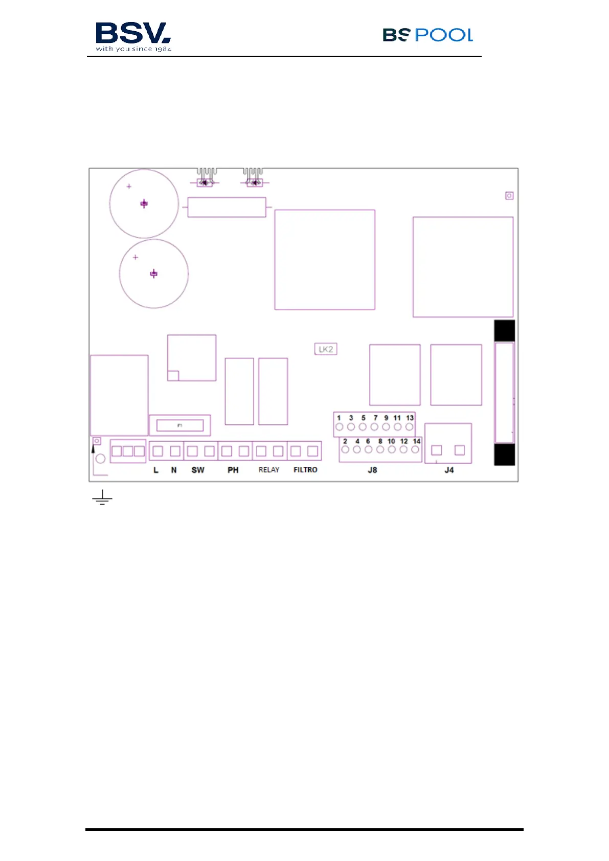
3.3- Electrical wiring diagram
3.3.1- EVOTOUCH series equipment
Earth connection
L, N: Supply 220v
SW: On / Off Switch
PH pH pump connection (For units with the AUTO kit)
RELAY: Dry contact relay
FILTER: Filter connection for Stop / Start mode
J4: Terminal block of cell
J8:
1- (yellow) Acid sensor (PH) 8- (blue) Temperature probe
2- (yellow) Acid sensor (PH) 9- (brown) ORP-
3- (purple) Cover 10- (orange) ORP+
4- (purple) Cover 11- (red) 12V free chlorine probe
5- (white) Water sensor (cell’s white cable) 12- (gray) Conductiviy (GND)
6- (white) External flow switch (5-6)* 13- (green) Conductivity (signal)
7- (blue) Temperature probe 14- (red) Conductivity (12v)
* activate the FLOW SWITCH operation in the Configuration Menu
K1: PH Relay
K4: Auxiliary relay
LK2: Stop/Start (see 3.3.2.1)
F1: Fuse