06/23
25
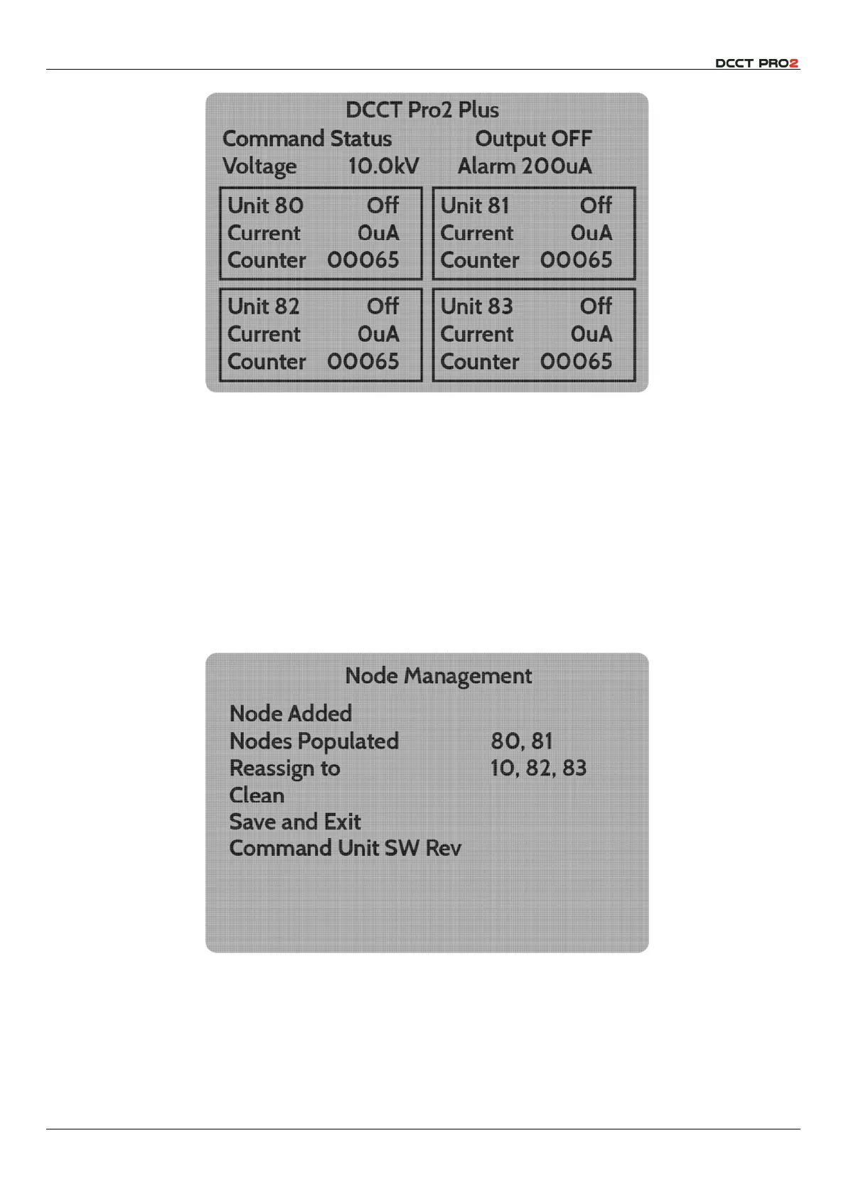
Fig 27– Home Screen with 4 Output Modules attached.
The four output unit windows on the whole screen are therefore respectively nodes 80 & 81 on the
upper row, and nodes 82 & 83 on the lower. Physical connection of an output unit to the network will
populate the next available node, and this is typically convenient.
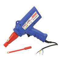
However, if it is desired to change the position of the output unit on the home screen, perhaps to reflect
the arrangement of electrodes being controlled from the User Interface, this can be carried out in the
Node Management
menu.
Node 80 will always be in the top left window – this process allows the unit that is connected to that
node to be assigned to a different node, and thus appear in a different location on the screen.
Every connected unit must have a node address. This menu allows the output units to be reallocated
as desired.
Fig 28 – Node Management Menu – two units attached.
Thus, if the installation has two connected output units, and it is desired to swap units, it is necessary to
move the unit in node 80 to e.g., node 82, then the unit attached to node 81 to node 80, and finally,
the first unit from node 82 to node 81.