Modules and their functions
9
Logamatic 4121, 4122 and 4126 - Subject to technical modifications.
70
9.1 ZM424 central module
The ZM424 module together with the FM455 module are
part of the standard equipment of the Logamatic 4121
control unit.
The ZM424 module must always be installed in the l.h.
slot 1. The FM455 module must always be installed
below the ZM424 in slot A.
The switches on the module only have service and
maintenance functions and only affect the 230 V
outputs.
If the switches are not set to automatic, a message to
this effect appears on the MEC2 programming unit and
fault indicator
0 lights up.
The control functions remain operational in manual
mode.
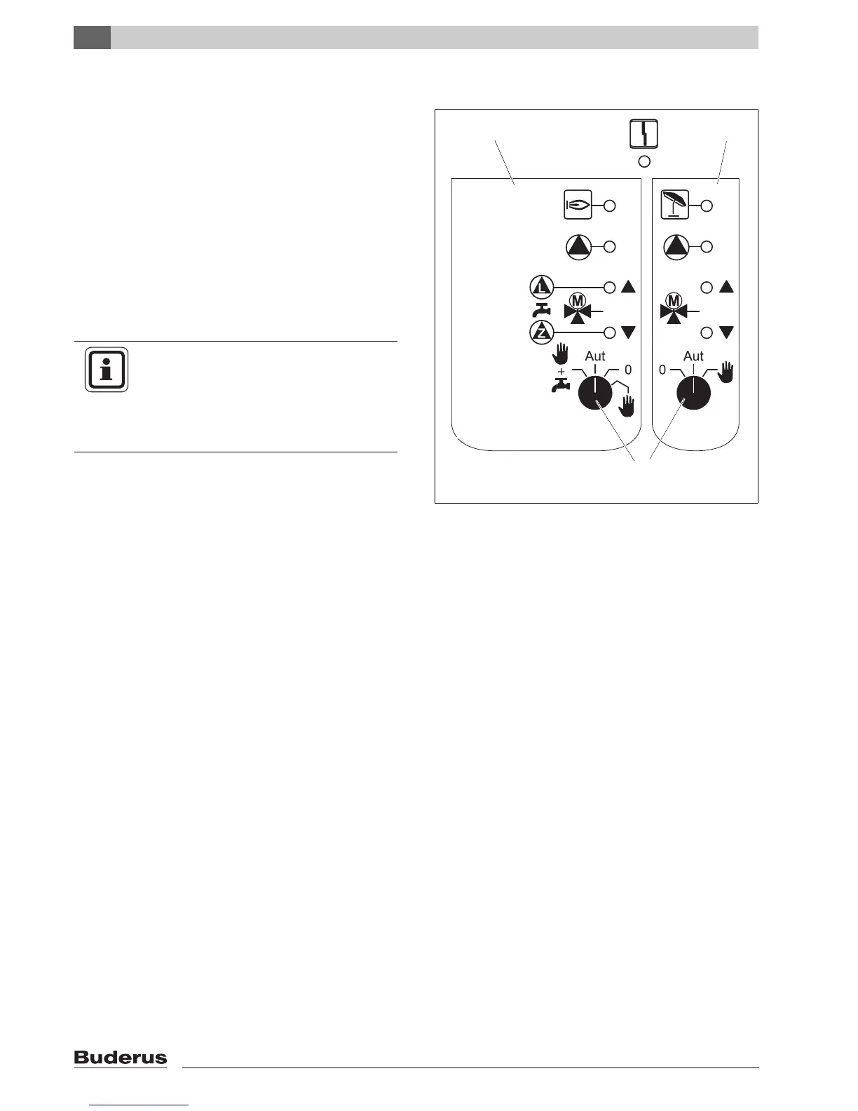
Fig. 20 ZM424
1 Boiler, heating circuit 1, DHW
2 Heating circ. 2
3 Switch
Display 0 General fault,
e.g. on-site faults,
sensor faults, external faults,
wiring faults, internal
module faults, manual mode.
The fault messages appear as plain text on
the MEC2 programming unit.
LEDs for the following functions:
Display a Burner operational
Display U "Mixer opens" (hotter)
Display V "Mixer closes" (colder)
Display 1 Heating circuit 2 in summer mode
Display 8 Heating circuit pump operational
Display x Cylinder primary pump operational
Display y DHW circulation pump operational
 Loading...


