Principles of operation
Logamatic EMS RC35 programming unit - Subject to technical modifications
12
4
4 Principles of operation
4.1 Display
The following elements appear on the display of the RC35 programming unit during standard
operation:
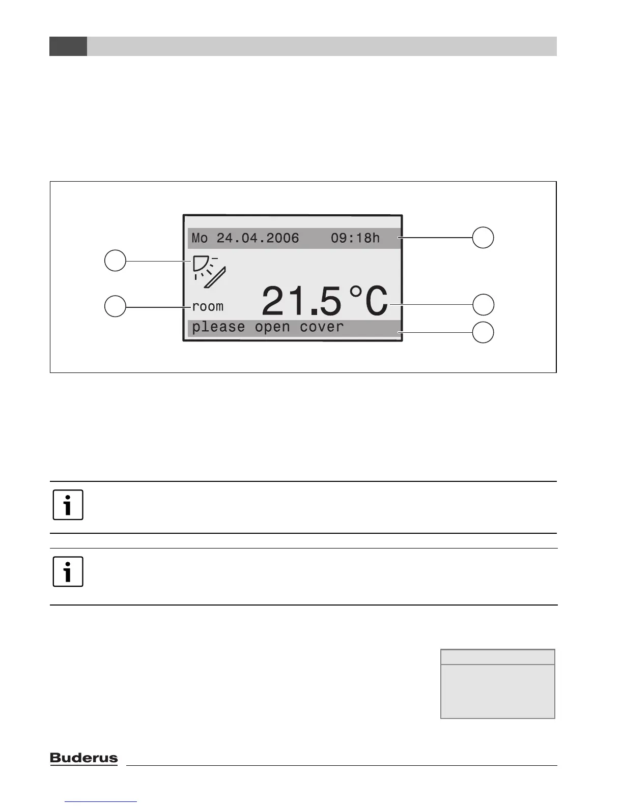
Fig. 1 Elements on the display
1 Top information row: standard display (factory setting: date and time)
2 Large display of room or boiler temperature
3 Bottom status row: displays various operating modes and indicates any error messages or service
messages
4 Solar symbol (if solar thermal system is installed and active)
4.2 Notes on functional scope
These instructions describe all the possible functions of the RC35. Some
of these functions may not be available, depending on which boiler and
combustion controller version are used. For more information, refer to the
relevant chapter. Contact your heating contractor for further details. To
check the version of the combustion controller used (here: UBA1.5), see
the info menu under INFO\VERSIONS (Æ page 20).
You can set (Æ page 29) which value is shown permanently in the first row of the
standard display (Æ Fig. 1, [1]).
If the programming unit is installed on the boiler, the room temperature cannot be
recorded. The boiler water temperature (boiler) is then displayed instead of the room
temperature [2].
2
3
4
2
1
6 720 618 414-01.1RS
INFO\VERSIONS
RC35 1.02
UBA1.5 1.21