5
Installation of the boiler
Logano plus SB615 Gas - We reserve the right to make any changes due to technical modifications.
15
5.5 Installing the minimum pressure
switch and minimum pressure
limiter
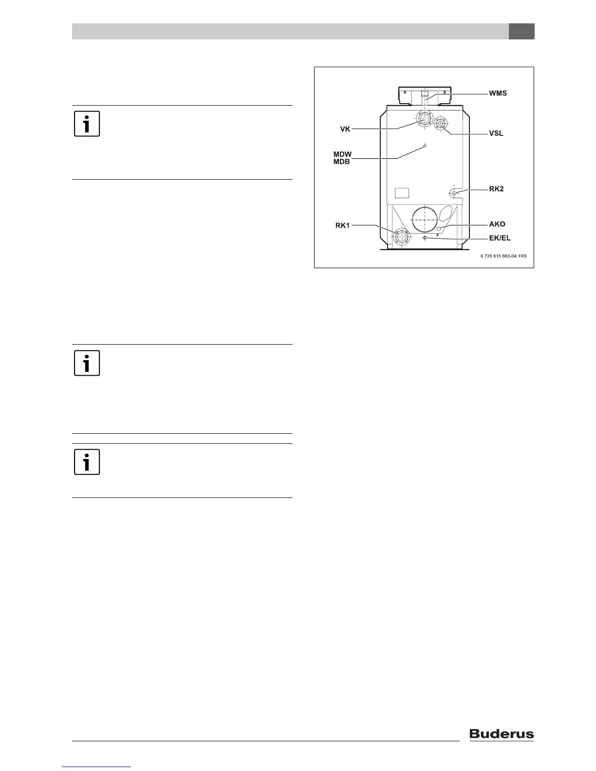
B Connect the minimum pressure monitor or minimum
pressure limiter (with R½ to R¼ connection piece
adapter) to the MDW/MDB connection on the boiler
(Æ Fig 5).
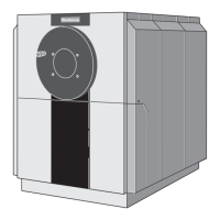
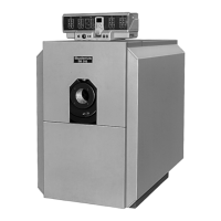
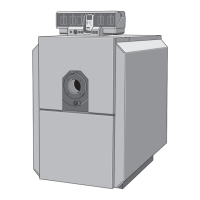
Fig. 5 Logano plus SB615 Gas boiler connections
5.6 Low water indicator (accesory),
fitting (400 – 600 kW)
B Seal the flow pipe for the low water indicator into the
2" LWI connection on the boiler (Æ Fig. 5).
B Fit the low water indicator onto the low water indicator
tube.
B If the LWI connection is not being used for the
installation of a low water indicator, remove the plastic
plug and close off the LWI connection with a blanking
plug.
Note that a minimum pressure monitor must
be connected for 145 kW to 240 kW!
For 310 kW (145 kW and higher in Poland)
a minimum pressure limiter (MDB) must be
installed. This requires an R½ to connection
piece adapter R¼ .
For Germany
B For boilers > 300 kW, install a low water
indicator or minimum pressure limiter as
required by DIN-EN 12 828.
B For installation and operation, refer to the
technical documents provided by the
manufacturer.
For Poland
B For boilers > 100 kW, equip the boiler
with a low water indicator as required by
PN-91/B-2414 (p2.5).