5
Installation of the boiler
Logano plus SB615 Gas - We reserve the right to make any changes due to technical modifications.
26
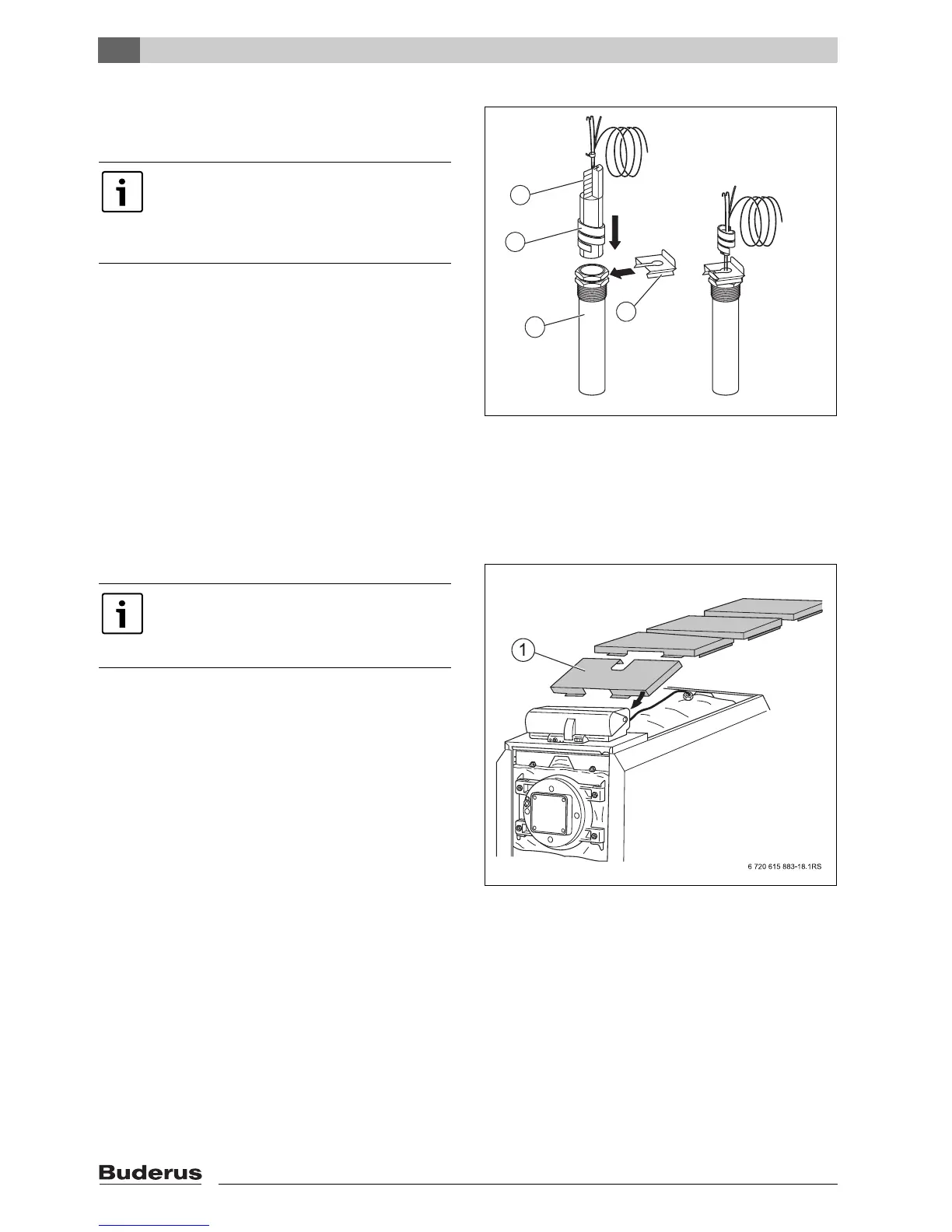
B The plastic coil [2] for holding together the temperature
sensor is pushed back automatically when it is
inserted.
B Coil up any excess cable, capillary tube and sensor
leads and place on the boiler body insulation.
B Connect the temperature sensors to the control unit.
Fig. 21 Inserting the plastic coil into the sensor well
1 Compensating spring
2 Plastic spiral
3 Sensor retainer
4 Sensor well
5.17 Fitting the boiler cover sections
Boiler sizes 145 kW to 400 kW
4 boiler cover sections
Boiler sizes 510 kW to 640 kW
5 boiler cover sections
B Loosely locate the boiler cover sections one after the
other on the right and left side panels.
Fig. 22 Fitting the boiler cover sections - Example
1 Recess for boiler sizes 400 kW and upwards
To ensure a good contact between sensor
well [4] and sensor surfaces, and thereby a
reliable temperature transfer, the
compensating spring [1] must be pushed in
between the sensors.
6720615883-32.1RS
1
2
3
4
From 400 kW upwards, the second cover
part is provided with a recess (Æ Fig. 22).
The rear parts are identical and are
positioned with their fold forward.