16
SERVICE (CONT.)
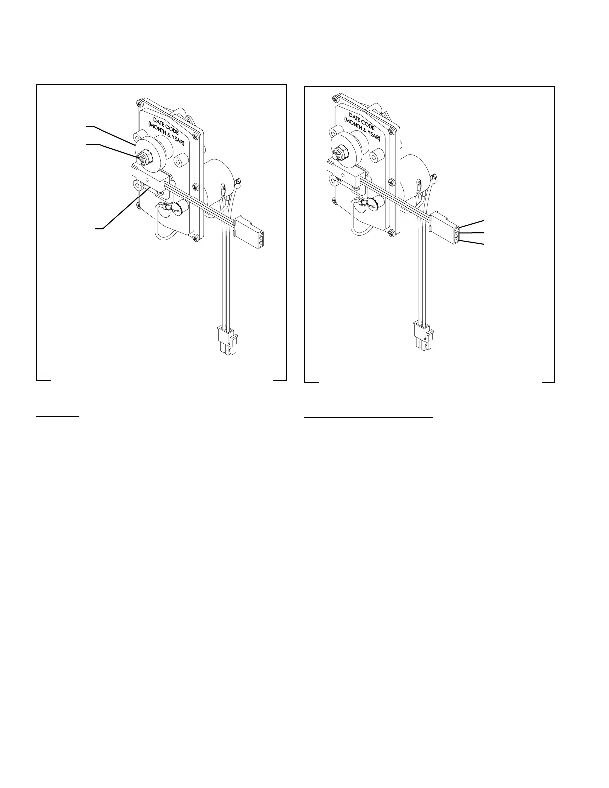
AUGER MOTOR PROXIMITY RPM SENSOR (IMIX-3, 4 & 5 only)
FIG. 7 AUGER MOTOR PROXIMITY SENSOR
MAGNET
PROXIMITY
SENSOR
NUT &
LOCKWASHER
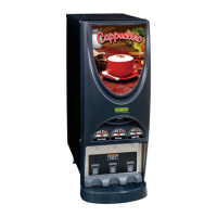
FIG. 8 PROXIMITY SENSOR TERMINALS
BLK - COMMON
GRN - SIGNAL
RED - +5VDC
Location:
The Proximity Sensor and Magnet are located on
the back side of the Auger Motor assembly.
Test Procedures:
1. Ensure the the nut and lockwasher are tightened
securely to prevent the Magnet from slipping, which
causes a false reading when testing.
2. With a voltmeter, back probe the RED and BLK
wires. The indication should be +5VDC.
3. Back probe the BLK and GRN wires. The indication
should be an alternating reading of 5-0-5-0VDC.
With power ON, the reading will actually fluctuate
in the 3VDC range.
If voltage is present as described, the Proximity RPM
Sensor is operating properly.
Removal and Replacement:
1. Disconnect the dispenser from the power source.
2. Disconnect the three pin connector from the main
wirring harnes of the motor being serviced.
3. Remove the #10 nut and lockwasher securing the
magnet hub to the auger motor shaft.
4. Remove the two #4-40 screws securing the sensor
to the auger motor housing.
5. Remove and discard faulty parts.
6. Install a new sensor to the motor housing using
the two #4-40 screws.
7. Install a new magnet hub using the #10 lockwasher
and nut. Tighten the nut securely to prevent the
magnet from slipping.
8. Connect the three pin connector to the dispenser
main wiring harness.
42032 060109