Bunn-O-Matic Corporation
5
Prepping Machine for Install
Step 1: Verify that all of the site requirements have been met.
Step 2: Unbox the machine and all the parts.
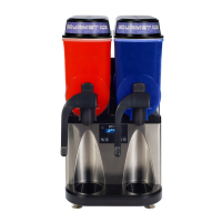
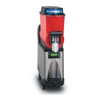
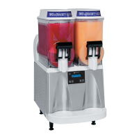
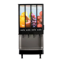
Step 3: Place the machine in the desired location on the counter. Do not lift the Ultra by the drum(s).
Step 4: Document the complete serial number of the machine.
Step 5: Remove and save the black plastic drum support(s). This will be used as a servicing jig later.
Step 6: Adjust the legs on the machine so that it is level or slightly lower in the front.
Step 7: Remove the shipping eye bolts, located on the bottom of the machine, from the compressor.
Bunn-O-Matic Corporation
5
Step 3: Place the machine in the desired location on the counter. Do not lift the Ultra by the drum(s).
Step 4: Document the complete serial number of the machine.
Step 5: Remove and save the black plastic drum support(s). This will be used as a servicing jig later.
Step 6: Adjust the legs on the machine so that it is level or slightly lower in the front.
Step 7: Remove the shipping eye bolts, located on the bottom of the machine, from the compressor.
Hopper Assembly
Electrical Install
Step 1: Plug machine into 120VAC outlet.
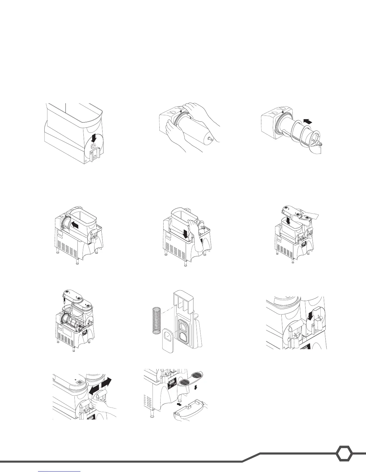
Step 1: Insert the auger nose
bushing from inside the hopper.
Step 2: Install the seal(s) over the
ange at the rear of the cooling drum(s)
and press the seal(s) rmly into place
as shown.
Step 3: Align the auger shaft(s) with
the auger(s). Push the auger(s) as far
as they will go and rotate so the at face
of the auger shaft is aligned with the at
face of the auger nose.
Step 4: Install the hopper over the
auger and cooling drum and slide it into
place.
Step 5: Push down until the hopper
lock plunger snaps into place.
Step 6: Set the hopper lid on the hop-
per with lamp cord at the back.
Step 7: Plug in the hopper lid lamp
cord.
Step 8: Position the faucet seal and
the return spring in the faucet valve.
Step 9: Slide the faucet valve assem-
bly into place on the hopper.
Step 10: Press down on the valve to
compress the spring. Position the faucet
handle over the faucet valve one side
at a time and snap into place on the
hopper.
Step 11: Install the drip tray and cover.