Ultra Training Manual
8
Installing Liquid Autoll Kits (Autoll ready Ultra-2)
BUNN-O-MATIC CORPORATION
POST OFFICE BOX 3227
SPRINGFIELD, ILLINOIS 62708-3227
PHONE: (217) 529-6601 FAX: (217) 529-6644
37570.0000E 10/11 ©2005 Bunn-O-Matic Corporation
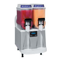
ULTRA-2
INSTRUCTIONS FOR INSTALLING
LIQUID AUTOFILL KITS
INTRODUCTION
These instructions are for installing the Liquid Autofill Kits on Autofill ready ULTRA-2 cold drink dispensers.
There are three different kits available:
37960.0000 ULTRA-2 Liquid Autofill Kit 120V with Separate Water Lines
37960.0001 ULTRA-2 Liquid Autofill Kit 120V without Water Lines
37960.0002 ULTRA-2 Liquid Autofill Kit 230V with Separate Water Lines
INSTRUCTIONS
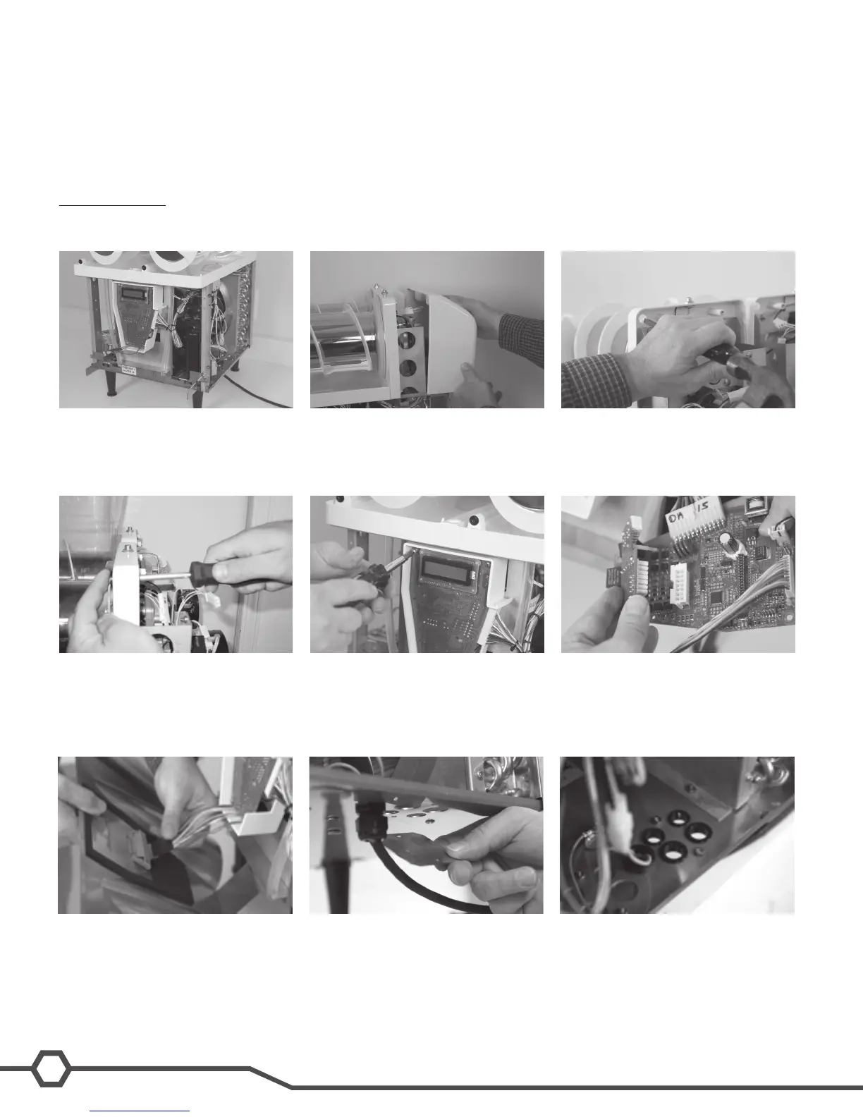
1. Unplug machine from power source before removing any panels.
2. Drain both hoppers and clean the machine if needed before proceeding.
8. Connect Auto Fill board to main board.
Be sure to snap the plastic stand off’s
completely into the main board.
7. Remove 4 screws holding in the main
circuit board.
6. Install level probe assembly into hole
and secure with nut provided.
5. With a standard screwdriver and a
hammer, punch out the hole needed
for the level probe. Repeat this step
for both sides.
4. Remove both motor covers and locate
.50” round knock out in top right area
of plastic drum mount.
3. Remove hoppers, drip tray, both side
panels and front panel.
2
INSTRUCTIONS (Continued)
14. Install valve and bracket assembly by
feeding the attached tubing through
the smaller snap bushings in the base
of the machine.
13. Remove top nut off of grounding stud
in the base of the machine, add on the
green grounding wire from the new har-
ness and reinstall the nut onto the stud.
Make sure that all the other grounding
wires remain on the ground stud.
12. Plug wire harness (supplied with kit)
into Auto Fill board connector and route
wires back into the machine.
11. Install provided bushings into product/
water holes to protect the tubing.
10. Remove hole covers from the base of
the machine as needed to route water
and product tubing through base.
9. Reinstall the main board into the
machine using the original mounting
screws.
17. Position the valve and bracket assembly
between the right front corner post and
the right side fan shroud and secure
with screws provided.
16. Route Pink and Tan wires up to level
probes and attach using nuts provided.
Pink is the right probe and Tan is the
left probe.
15. Connect the wires to the fill valves both
water and product as needed according
to the wiring schematic provided. Red
and White wires to the right valve(s),
Blue and white wires to the left valve(s).
Please note that Left and Right are from
the front of the machine, Users left and
right.
37570 072706