LOWLANDER HD MK2 & WIDEBODY MANURE SPREADER – INSTRUCTION & SPARES MANUAL
Page 76
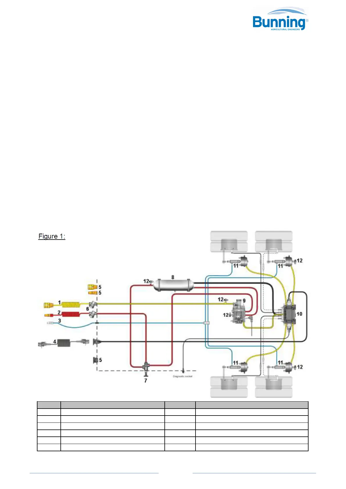
6.3.3 TWO-LINE TRAILER AIR BRAKING SYSTEMS
The two-line trailer braking system is based on HGV trailer braking systems which were designed to meet the
European Council Directive 71/320/EEC. These systems use one red air line (known as a supply or emergency line)
which is permanently pressurized by the tractor when coupled to the trailer, and one yellow line (known as the service
or control line) which has a variable pressure. This variable pressure is controlled by the driver and is determined by
how quickly the driver wishes to slow down, or whether the tractor’s handbrake is applied. Also, this is often fully
pressurized when the tractor’s ignition is switched OFF.
Figure 1 is a typical layout of a tandem-axle trailer, with a combined RELSV and ABS. The RELSV is mounted between
the axles and connects to either a telescopic pole or an angle iron which fits between them. The angle iron system is
sometimes supported by rubber bobbings.
For a two sensor ABS system the front axle should be ABS sensed, and the layout below also shows extra (optional)
ABS sensors connected to the rear axle. These extra ABS sensors should ensure that the rear axle does not lock.
Where no ABS system is fitted, which is the case for all our spreaders, then the RELSV delivers the air directly to the
brake chambers from each of its delivery ports. (The brake chambers shown on the diagram are also fitted with
hydraulic brakes [dual air & hydraulic brakes], to suit the tractors that do not provide trailer air braking.)
WHEN THE TRACTOR AND THE TRAILER BOTH HAVE AIR AND HYDRAULIC BRAKE CONNECTIONS, DO NOT CONNECT
BOTH OF THEM – ONLY ONE BRAKE SYSTEM CAN BE CONNECTED AND USED AT A TIME.
With a tri-axle trailer the RELSV is generally fitted above the centre axle and connected directly to it, so no telescopic
pole, angle iron or bobbings are required.
For a single axle trailer, with no moving point to connect the automatic RELSV, a manually controlled 3-position load
sensing valve is fitted to meet the 2015/68 EU directive. The valve compasses the Manual LP Valve and the Relay
Emergency Valve with the following positions: UNLADEDN, HALF LADEN and FULL LADEN.
KEY DESCRIPTION KEY DESCRIPTION
1 YELLOW LINE SUSIE 7 SHUNT VALVE
2 RED LINE SUSIE 8 AIR TANK
3 HYDRAULIC BRAKE HOSE 9 RELSV
4 ABS POWER SUSIE (5 CORE) 10 ABS MODULATOR VALVE + CABLES
5 DUMMY COUPLINGS 11 AIR + HYDRAULIC BRAKE CHAMBERS
6 FILTERS 12 PNEUMATIC TEST POINTS